How to Use MMA8452Q: Examples, Pinouts, and Specs
Introduction
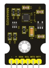
The MMA8452Q is a low-power, 3-axis accelerometer manufactured by Keyestudio. It is designed to measure acceleration in three dimensions (X, Y, and Z) and provides digital output via I2C or SPI interfaces. This component is widely used in motion sensing applications, including orientation detection, free-fall detection, and gesture recognition. Its compact size and low power consumption make it ideal for portable and battery-powered devices.
Explore Projects Built with MMA8452Q


Explore Projects Built with MMA8452Q
Common Applications
- Smartphones and wearable devices for motion tracking
- Gaming controllers for gesture recognition
- Robotics for tilt and orientation sensing
- Industrial equipment for vibration monitoring
- Automotive systems for impact and motion detection
Technical Specifications
The MMA8452Q is a versatile accelerometer with the following key specifications:
| Parameter | Value |
|---|---|
| Operating Voltage | 1.95V to 3.6V |
| Communication Interface | I2C (up to 400 kHz) or SPI |
| Measurement Range | ±2g, ±4g, ±8g (configurable) |
| Output Data Rate (ODR) | 1.56 Hz to 800 Hz |
| Sensitivity | 1024 counts/g (±2g mode) |
| Power Consumption | 6 µA in standby, 165 µA in active |
| Operating Temperature | -40°C to +85°C |
| Package Type | QFN-16 (3 mm x 3 mm x 1 mm) |
Pin Configuration
The MMA8452Q has 16 pins, with the following configuration:
| Pin Number | Pin Name | Description |
|---|---|---|
| 1 | VDD | Power supply (1.95V to 3.6V) |
| 2 | VSS | Ground |
| 3 | SDA | I2C data line |
| 4 | SCL | I2C clock line |
| 5 | INT1 | Interrupt 1 output |
| 6 | INT2 | Interrupt 2 output |
| 7 | NC | Not connected |
| 8 | NC | Not connected |
| 9 | NC | Not connected |
| 10 | NC | Not connected |
| 11 | NC | Not connected |
| 12 | NC | Not connected |
| 13 | NC | Not connected |
| 14 | NC | Not connected |
| 15 | NC | Not connected |
| 16 | NC | Not connected |
Usage Instructions
Connecting the MMA8452Q to an Arduino UNO
The MMA8452Q communicates via the I2C protocol, which requires only two data lines: SDA and SCL. Below is a simple guide to connect the MMA8452Q to an Arduino UNO:
Connections:
- Connect the VDD pin of the MMA8452Q to the 3.3V pin on the Arduino.
- Connect the VSS pin of the MMA8452Q to the GND pin on the Arduino.
- Connect the SDA pin of the MMA8452Q to the A4 pin on the Arduino (I2C data line).
- Connect the SCL pin of the MMA8452Q to the A5 pin on the Arduino (I2C clock line).
Pull-up Resistors:
- The I2C lines (SDA and SCL) require pull-up resistors (typically 4.7 kΩ). If your breakout board does not include these resistors, you must add them externally.
Arduino Code Example: Below is an example Arduino sketch to read acceleration data from the MMA8452Q:
#include <Wire.h> // Include the Wire library for I2C communication

#define MMA8452Q_ADDRESS 0x1D // Default I2C address of the MMA8452Q

void setup() {
  Wire.begin(); // Initialize I2C communication
  Serial.begin(9600); // Start serial communication for debugging

  // Initialize the MMA8452Q
  Wire.beginTransmission(MMA8452Q_ADDRESS);
  Wire.write(0x2A); // CTRL_REG1 register
  Wire.write(0x01); // Set the device to active mode
  Wire.endTransmission();
}

void loop() {
  int16_t x, y, z;

  // Request 6 bytes of acceleration data from the MMA8452Q
  Wire.beginTransmission(MMA8452Q_ADDRESS);
  Wire.write(0x01); // Start reading from the OUT_X_MSB register
  Wire.endTransmission(false);
  Wire.requestFrom(MMA8452Q_ADDRESS, 6);

  if (Wire.available() == 6) {
    x = (Wire.read() << 8) | Wire.read(); // Combine MSB and LSB for X-axis
    y = (Wire.read() << 8) | Wire.read(); // Combine MSB and LSB for Y-axis
    z = (Wire.read() << 8) | Wire.read(); // Combine MSB and LSB for Z-axis
  }

  // Print the acceleration values to the Serial Monitor
  Serial.print("X: ");
  Serial.print(x / 1024.0); // Convert to g
  Serial.print(" g, Y: ");
  Serial.print(y / 1024.0); // Convert to g
  Serial.print(" g, Z: ");
  Serial.print(z / 1024.0); // Convert to g
  Serial.println(" g");

  delay(100); // Wait 100 ms before the next reading
}
Important Considerations
- Power Supply: Ensure the MMA8452Q is powered with a voltage between 1.95V and 3.6V. Exceeding this range may damage the component.
- I2C Address: The default I2C address of the MMA8452Q is
0x1D. If theSA0pin is pulled high, the address changes to0x1C. - Interrupts: The INT1 and INT2 pins can be configured for various interrupt functions, such as motion detection or free-fall detection.
Troubleshooting and FAQs
Common Issues
No Data from the Sensor:
- Ensure the I2C connections (SDA and SCL) are correct and have pull-up resistors.
- Verify the I2C address of the MMA8452Q. Use an I2C scanner sketch to detect the device.
Incorrect or Unstable Readings:
- Check the power supply voltage and ensure it is within the specified range.
- Verify that the sensor is properly mounted and not subject to excessive vibration.
Arduino Freezes or Crashes:
- Ensure the I2C lines are not shorted or improperly connected.
- Avoid using long wires for I2C communication, as this can cause signal degradation.
FAQs
Q: Can the MMA8452Q detect free-fall events?
A: Yes, the MMA8452Q has a built-in free-fall detection feature that can be configured using its registers.
Q: What is the maximum sampling rate of the MMA8452Q?
A: The MMA8452Q supports output data rates (ODR) up to 800 Hz.
Q: Can I use the MMA8452Q with a 5V microcontroller?
A: Yes, but you must use a level shifter to step down the 5V I2C signals to 3.3V to avoid damaging the sensor.
Q: How do I change the measurement range?
A: The measurement range (±2g, ±4g, ±8g) can be configured by writing to the XYZ_DATA_CFG register.
This concludes the documentation for the MMA8452Q. For further assistance, refer to the official datasheet or contact Keyestudio support.