Cirkit Designer Logo
Cirkit Designer
Your all-in-one circuit design IDE
Home / 
Component Documentation

How to Use PM07 Power Module: Examples, Pinouts, and Specs

Image of PM07 Power Module
Cirkit Designer LogoDesign with PM07 Power Module in Cirkit Designer

Introduction

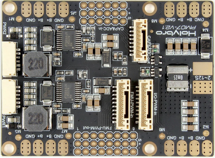
The PM07 Power Module, manufactured by HolyBro (Part ID: PM07), is designed to provide a stable power supply to electronic circuits. It typically converts a higher voltage input to a lower, regulated output suitable for sensitive components. This module is essential in applications where a reliable and consistent power source is required, such as in robotics, drones, and various embedded systems.

Explore Projects Built with PM07 Power Module

Use Cirkit Designer to design, explore, and prototype these projects online. Some projects support real-time simulation. Click "Open Project" to start designing instantly!
DC-DC Converter and Relay Module Power Distribution System
Image of relay: A project utilizing PM07 Power Module in a practical application
This circuit consists of a DC-DC converter powering a 6-channel power module, which in turn supplies 5V to a 2-relay module. The power module distributes the converted voltage to the relay module, enabling it to control external devices.
Cirkit Designer LogoOpen Project in Cirkit Designer
Solar-Powered Battery Charging Circuit with LED Indicator
Image of hybrid torch: A project utilizing PM07 Power Module in a practical application
This circuit appears to be a solar-powered charging and power supply system with a battery backup. A TP4056 module is used for charging the 3.7V battery from the solar panel via a bridge rectifier, ensuring proper battery management. The system can power an LED and a motor, with a rocker switch to control the LED, and diodes are used to provide correct polarity and prevent backflow of current.
Cirkit Designer LogoOpen Project in Cirkit Designer
Solar-Powered Battery Charging and Monitoring System with TP4056 and 7-Segment Voltmeter
Image of CKT: A project utilizing PM07 Power Module in a practical application
This circuit is a solar-powered battery charging and monitoring system. It uses a TP4056 module to charge a Li-ion 18650 battery from solar cells and a DC generator, with multiple LEDs and a voltmeter to indicate the charging status and battery voltage. The circuit also includes transistors and resistors to control the LEDs and a bridge rectifier for AC to DC conversion.
Cirkit Designer LogoOpen Project in Cirkit Designer
Battery-Powered UPS System with Waveshare UPS 3S and Solar Charger
Image of Copy of s: A project utilizing PM07 Power Module in a practical application
This circuit is a power management system that integrates a 12V power supply, a solar charger power bank, and multiple Li-ion batteries to provide a stable power output. The Waveshare UPS 3S manages the input from the power sources and batteries, ensuring continuous power delivery. The MRB045 module is used to interface the solar charger with the rest of the system.
Cirkit Designer LogoOpen Project in Cirkit Designer

Explore Projects Built with PM07 Power Module

Use Cirkit Designer to design, explore, and prototype these projects online. Some projects support real-time simulation. Click "Open Project" to start designing instantly!
Image of relay: A project utilizing PM07 Power Module in a practical application
DC-DC Converter and Relay Module Power Distribution System
This circuit consists of a DC-DC converter powering a 6-channel power module, which in turn supplies 5V to a 2-relay module. The power module distributes the converted voltage to the relay module, enabling it to control external devices.
Cirkit Designer LogoOpen Project in Cirkit Designer
Image of hybrid torch: A project utilizing PM07 Power Module in a practical application
Solar-Powered Battery Charging Circuit with LED Indicator
This circuit appears to be a solar-powered charging and power supply system with a battery backup. A TP4056 module is used for charging the 3.7V battery from the solar panel via a bridge rectifier, ensuring proper battery management. The system can power an LED and a motor, with a rocker switch to control the LED, and diodes are used to provide correct polarity and prevent backflow of current.
Cirkit Designer LogoOpen Project in Cirkit Designer
Image of CKT: A project utilizing PM07 Power Module in a practical application
Solar-Powered Battery Charging and Monitoring System with TP4056 and 7-Segment Voltmeter
This circuit is a solar-powered battery charging and monitoring system. It uses a TP4056 module to charge a Li-ion 18650 battery from solar cells and a DC generator, with multiple LEDs and a voltmeter to indicate the charging status and battery voltage. The circuit also includes transistors and resistors to control the LEDs and a bridge rectifier for AC to DC conversion.
Cirkit Designer LogoOpen Project in Cirkit Designer
Image of Copy of s: A project utilizing PM07 Power Module in a practical application
Battery-Powered UPS System with Waveshare UPS 3S and Solar Charger
This circuit is a power management system that integrates a 12V power supply, a solar charger power bank, and multiple Li-ion batteries to provide a stable power output. The Waveshare UPS 3S manages the input from the power sources and batteries, ensuring continuous power delivery. The MRB045 module is used to interface the solar charger with the rest of the system.
Cirkit Designer LogoOpen Project in Cirkit Designer

Common Applications and Use Cases

  • Drones and UAVs: Provides stable power to flight controllers and other onboard electronics.
  • Robotics: Ensures consistent power supply to motors, sensors, and control units.
  • Embedded Systems: Powers microcontrollers, sensors, and other peripherals.
  • Prototyping and Development: Useful in breadboard and development board projects, including Arduino-based projects.

Technical Specifications

Key Technical Details

Parameter Value
Input Voltage 7V - 42V
Output Voltage 5.3V ± 0.1V
Maximum Current 3A
Power Rating 15W
Dimensions 25mm x 21mm x 9mm
Weight 9g
Connector Type XT60 for input, 6-pin DF13 for output

Pin Configuration and Descriptions

XT60 Connector (Input)

Pin Description
1 Positive Voltage
2 Ground

6-pin DF13 Connector (Output)

Pin Description
1 VCC (5.3V)
2 Ground
3 Current Sense
4 Voltage Sense
5 Ground
6 VCC (5.3V)

Usage Instructions

How to Use the PM07 Power Module in a Circuit

  1. Connect the Input:

    • Connect the higher voltage power source (7V - 42V) to the XT60 connector. Ensure correct polarity to avoid damage.
  2. Connect the Output:

    • Use the 6-pin DF13 connector to connect the output to your circuit. Pins 1 and 6 provide the regulated 5.3V output, while pins 2 and 5 are ground.
  3. Voltage and Current Sensing:

    • Pins 3 and 4 on the DF13 connector can be used for current and voltage sensing, respectively. These can be connected to an ADC (Analog-to-Digital Converter) on a microcontroller for monitoring purposes.

Important Considerations and Best Practices

  • Heat Dissipation: Ensure adequate ventilation or cooling, especially if operating near the maximum current rating.
  • Polarity: Double-check connections to avoid reverse polarity, which can damage the module.
  • Load Capacity: Do not exceed the maximum current rating of 3A to prevent overheating and potential failure.
  • Secure Connections: Use appropriate connectors and secure connections to prevent accidental disconnections during operation.

Troubleshooting and FAQs

Common Issues and Solutions

  1. No Output Voltage:

    • Check Input Voltage: Ensure the input voltage is within the specified range (7V - 42V).
    • Verify Connections: Double-check all connections, especially the input polarity.
  2. Overheating:

    • Reduce Load: Ensure the current draw does not exceed 3A.
    • Improve Cooling: Add a heatsink or improve ventilation around the module.
  3. Fluctuating Output Voltage:

    • Stable Input: Ensure the input voltage is stable and within the specified range.
    • Check Load: Ensure the load is not causing excessive current spikes.

FAQs

Q: Can I use the PM07 Power Module with an Arduino UNO? A: Yes, the PM07 can be used to power an Arduino UNO. Connect the 5.3V output to the 5V pin on the Arduino and ground to ground.

Q: How do I monitor the current and voltage using the PM07? A: Connect the current sense (pin 3) and voltage sense (pin 4) pins to the ADC pins on your microcontroller. Use appropriate code to read and interpret the values.

Example Code for Arduino UNO

// Example code to read voltage and current from PM07 Power Module
const int voltagePin = A0; // Voltage sense pin
const int currentPin = A1; // Current sense pin

void setup() {
  Serial.begin(9600); // Initialize serial communication
  pinMode(voltagePin, INPUT);
  pinMode(currentPin, INPUT);
}

void loop() {
  int voltageValue = analogRead(voltagePin); // Read voltage
  int currentValue = analogRead(currentPin); // Read current

  // Convert ADC values to actual voltage and current
  float voltage = (voltageValue / 1023.0) * 5.0 * (42.0 / 5.0); // Adjust as needed
  float current = (currentValue / 1023.0) * 5.0 * (3.0 / 5.0); // Adjust as needed

  Serial.print("Voltage: ");
  Serial.print(voltage);
  Serial.println(" V");

  Serial.print("Current: ");
  Serial.print(current);
  Serial.println(" A");

  delay(1000); // Wait for 1 second before next reading
}

This documentation provides a comprehensive guide to the PM07 Power Module, ensuring users can effectively integrate and troubleshoot this component in their projects.