
How to Use Thermostat Temperature Switch: Examples, Pinouts, and Specs
 Design with Thermostat Temperature Switch in Cirkit Designer
Introduction
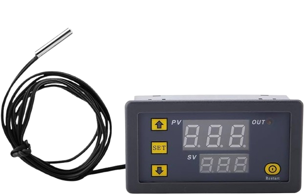
The Thermostat Temperature Switch is a device designed to regulate temperature by automatically switching heating or cooling systems on or off based on a predefined temperature setting. It is widely used in HVAC systems, home appliances, industrial equipment, and temperature-sensitive environments. This component ensures energy efficiency and maintains optimal temperature conditions.
Explore Projects Built with Thermostat Temperature Switch
 Open Project in Cirkit Designer
 Open Project in Cirkit Designer
 Open Project in Cirkit Designer
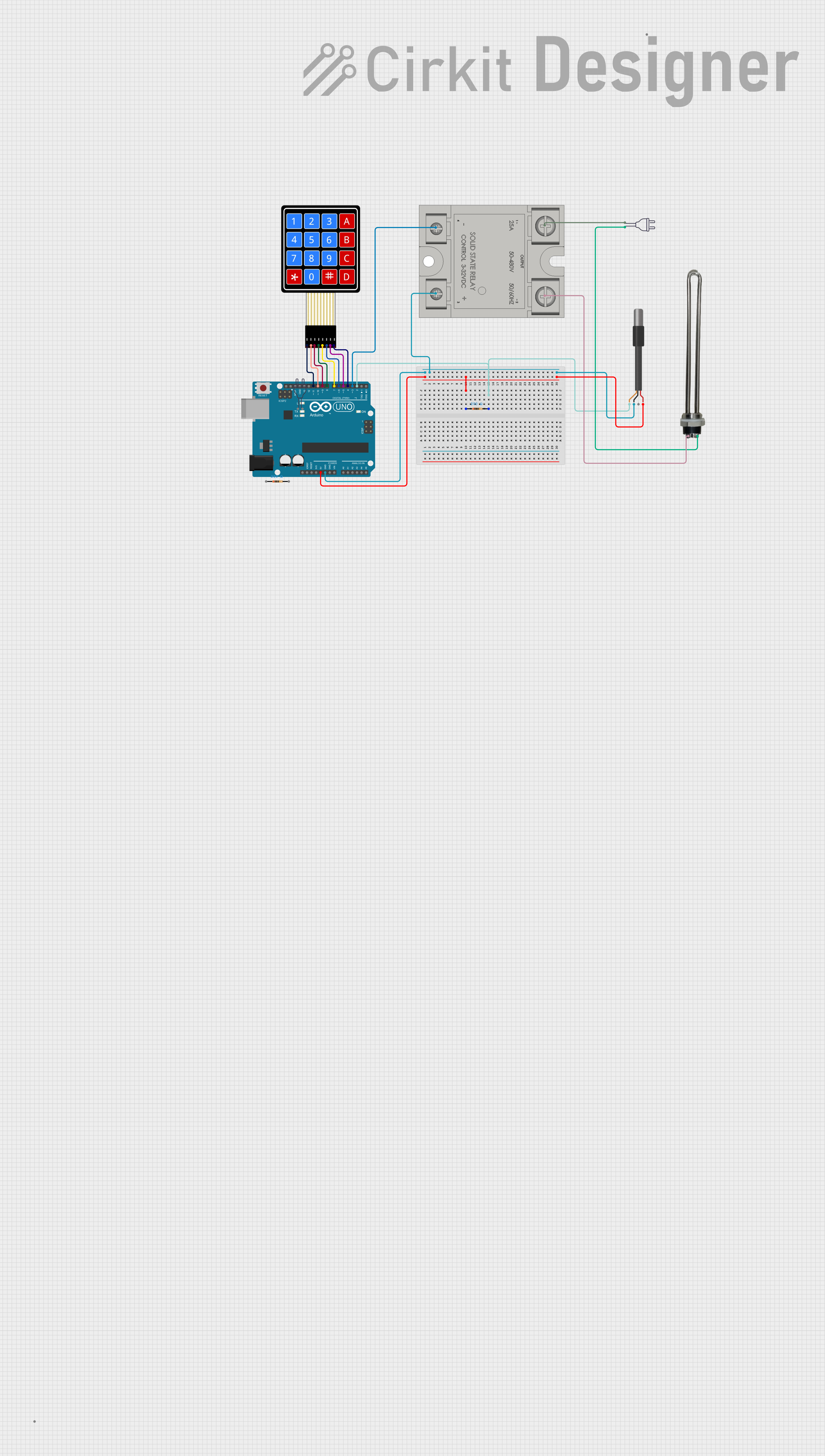 Open Project in Cirkit Designer
Explore Projects Built with Thermostat Temperature Switch
Open Project in Cirkit DesignerOpen Project in Cirkit DesignerOpen Project in Cirkit DesignerOpen Project in Cirkit DesignerCommon Applications
- Home heating and cooling systems (e.g., furnaces, air conditioners)
- Industrial temperature control systems
- Refrigerators and freezers
- Incubators and greenhouses
- Water heaters and boilers
Technical Specifications
Key Technical Details
- Operating Voltage: 12V DC or 24V AC (varies by model)
- Switching Current: Up to 10A
- Temperature Range: -30°C to 125°C (-22°F to 257°F)
- Accuracy: ±1°C
- Hysteresis: Configurable (typically 1°C to 5°C)
- Output Type: Relay (Normally Open or Normally Closed)
- Sensor Type: Built-in or external thermistor (NTC or PTC)
Pin Configuration and Descriptions
Below is a typical pinout for a Thermostat Temperature Switch with a relay output:
| Pin | Name | Description |
|---|---|---|
| 1 | VCC | Power supply input (e.g., 12V DC or 24V AC). |
| 2 | GND | Ground connection. |
| 3 | TEMP_SENSOR | Input for an external temperature sensor (if applicable). |
| 4 | RELAY_NO | Normally Open (NO) relay output for controlling external devices. |
| 5 | RELAY_NC | Normally Closed (NC) relay output for controlling external devices. |
| 6 | RELAY_COM | Common terminal for the relay. |
Note: Pin configurations may vary depending on the specific model. Always refer to the manufacturer's datasheet for exact details.
Usage Instructions
How to Use the Component in a Circuit
- Power Supply: Connect the VCC pin to a suitable power source (e.g., 12V DC) and the GND pin to ground.
- Temperature Sensor: If the thermostat requires an external sensor, connect it to the TEMP_SENSOR pin. Ensure the sensor is placed in the area where temperature monitoring is needed.
- Relay Connections:
- For devices that should turn on when the temperature exceeds the setpoint, connect the load to RELAY_NO and RELAY_COM.
- For devices that should turn off when the temperature exceeds the setpoint, connect the load to RELAY_NC and RELAY_COM.
- Set Temperature: Adjust the temperature setpoint using the onboard potentiometer or digital interface (if available).
- Hysteresis Adjustment: Configure the hysteresis (if supported) to prevent frequent switching.
Important Considerations and Best Practices
- Ensure the power supply voltage matches the component's requirements to avoid damage.
- Use a flyback diode across the relay coil to protect the circuit from voltage spikes.
- Place the temperature sensor in a location free from direct sunlight or airflow for accurate readings.
- Avoid exceeding the maximum current rating of the relay to prevent overheating or failure.
- If using with an Arduino or microcontroller, ensure proper isolation between the relay and control circuit.
Example: Connecting to an Arduino UNO
Below is an example of how to use the Thermostat Temperature Switch with an Arduino UNO to monitor temperature and control a fan:
Circuit Connections
- Connect the VCC and GND pins of the thermostat to the Arduino's 5V and GND pins.
- Connect the RELAY_NO and RELAY_COM pins to the fan's power circuit.
- Optionally, connect the TEMP_SENSOR pin to an external thermistor.
Arduino Code
// Example code to monitor temperature and control a fan using a thermostat switch

const int relayPin = 7; // Pin connected to the relay control
const int tempSensorPin = A0; // Analog pin for external temperature sensor (if used)

void setup() {
  pinMode(relayPin, OUTPUT); // Set relay pin as output
  digitalWrite(relayPin, LOW); // Ensure relay is off initially
  Serial.begin(9600); // Initialize serial communication for debugging
}

void loop() {
  int tempReading = analogRead(tempSensorPin); // Read temperature sensor value
  float voltage = tempReading * (5.0 / 1023.0); // Convert to voltage
  float temperature = (voltage - 0.5) * 100.0; // Convert to Celsius (example for LM35 sensor)

  Serial.print("Temperature: ");
  Serial.print(temperature);
  Serial.println(" °C");

  // Example logic: Turn on fan if temperature exceeds 30°C
  if (temperature > 30.0) {
    digitalWrite(relayPin, HIGH); // Activate relay
  } else {
    digitalWrite(relayPin, LOW); // Deactivate relay
  }

  delay(1000); // Wait 1 second before next reading
}
Note: Modify the code as needed based on the specific temperature sensor and application.
Troubleshooting and FAQs
Common Issues and Solutions
Relay Not Switching:
- Ensure the power supply voltage matches the thermostat's requirements.
- Check the relay connections and ensure the load is properly connected.
- Verify that the temperature setpoint and hysteresis settings are correct.
Inaccurate Temperature Readings:
- Ensure the temperature sensor is properly connected and placed in an appropriate location.
- Check for loose or damaged wires.
- If using an external sensor, verify its compatibility with the thermostat.
Frequent Switching:
- Adjust the hysteresis setting to reduce the frequency of switching.
- Ensure the temperature sensor is not exposed to rapid temperature changes (e.g., drafts).
No Output from Relay:
- Confirm that the relay is functional by testing it with a multimeter.
- Check the load's power requirements and ensure they are within the relay's rating.
FAQs
Q: Can I use the thermostat with a 220V AC load?
A: Yes, but ensure the relay's voltage and current ratings are suitable for the load. Use proper isolation and safety precautions.
Q: How do I adjust the temperature setpoint?
A: Most thermostats have an onboard potentiometer or digital interface for adjusting the setpoint. Refer to the specific model's manual for instructions.
Q: Can I use the thermostat without an external sensor?
A: Yes, if the thermostat has a built-in sensor. For models requiring an external sensor, one must be connected.
Q: What is hysteresis, and why is it important?
A: Hysteresis is the difference between the temperature at which the relay turns on and off. It prevents frequent switching, which can damage the relay or connected devices.