How to Use 3 Phase Solar Inverter: Examples, Pinouts, and Specs
Introduction
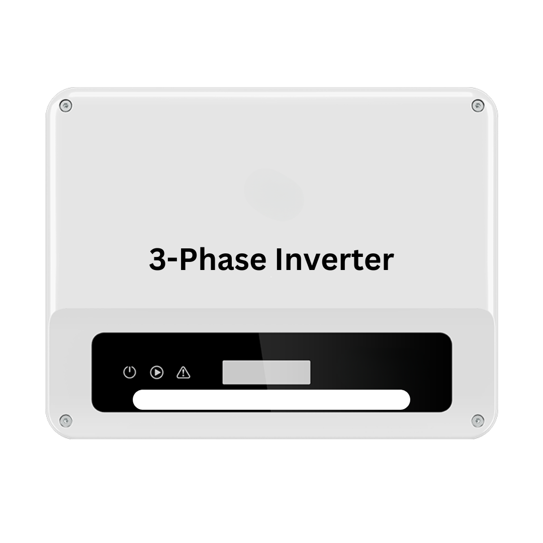
The 3 Phase Solar Inverter is a critical component in solar power systems, designed to convert the direct current (DC) output from solar panels into alternating current (AC) suitable for use in three-phase electrical systems. This type of inverter is commonly used in commercial and industrial solar power installations where three-phase power is required to run heavy machinery and equipment efficiently.
Explore Projects Built with 3 Phase Solar Inverter

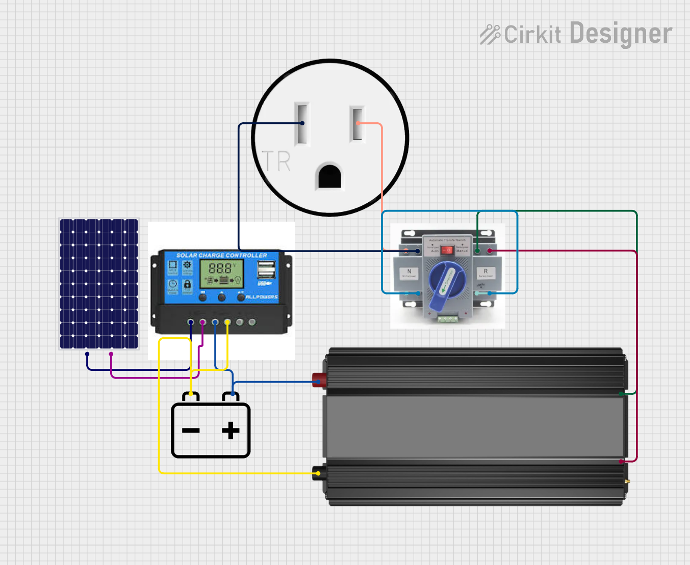
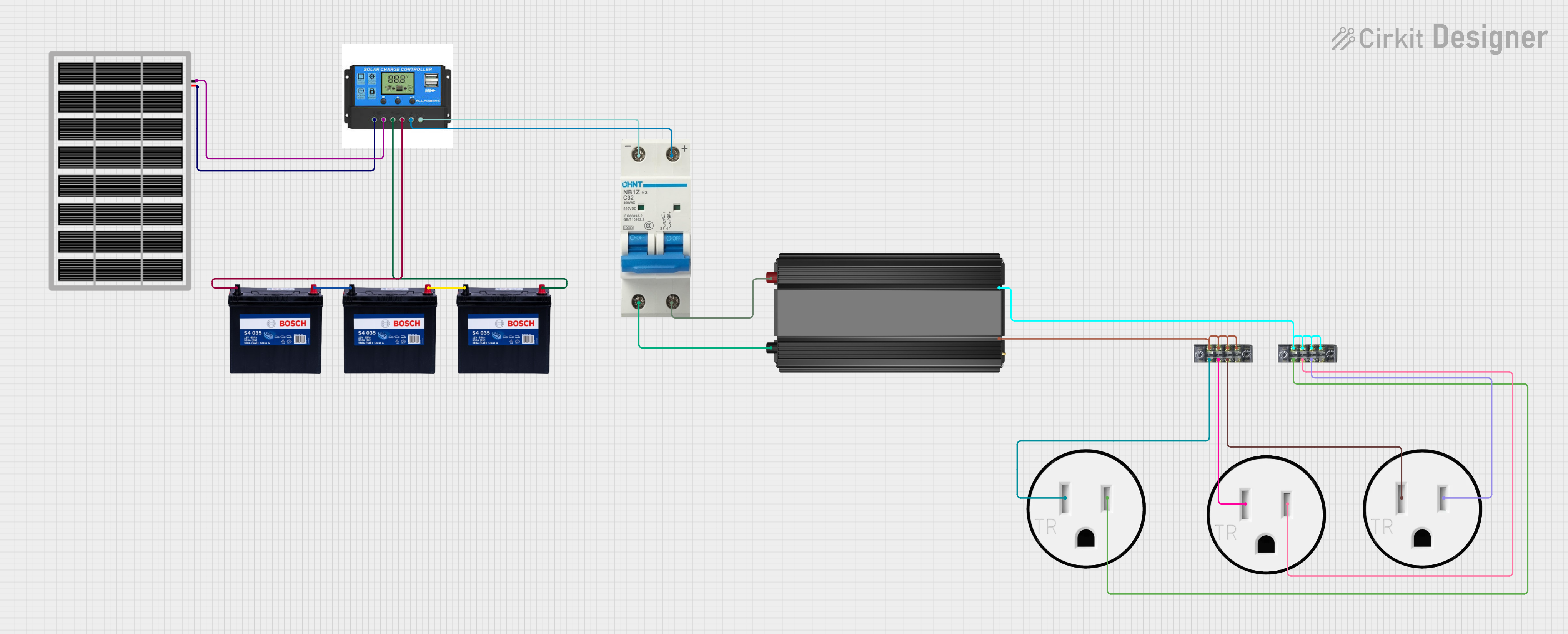

Explore Projects Built with 3 Phase Solar Inverter
Common Applications and Use Cases
- Commercial Solar Power Systems: Used in large-scale solar installations for businesses.
- Industrial Solar Power Systems: Powers heavy machinery and industrial equipment.
- Grid-Tied Solar Systems: Integrates with the electrical grid to supply power and reduce energy costs.
- Off-Grid Solar Systems: Provides power in remote locations without access to the electrical grid.
Technical Specifications
Key Technical Details
| Parameter | Value |
|---|---|
| Input Voltage Range | 300V - 1000V DC |
| Output Voltage | 400V AC (three-phase) |
| Output Frequency | 50/60 Hz |
| Maximum Output Power | 10 kW - 100 kW (model dependent) |
| Efficiency | Up to 98% |
| Operating Temperature | -25°C to 60°C |
| Cooling Method | Forced air cooling |
| Communication Ports | RS485, Ethernet, Wi-Fi |
Pin Configuration and Descriptions
| Pin Number | Pin Name | Description |
|---|---|---|
| 1 | DC+ | Positive DC input from solar panels |
| 2 | DC- | Negative DC input from solar panels |
| 3 | AC L1 | AC output phase 1 |
| 4 | AC L2 | AC output phase 2 |
| 5 | AC L3 | AC output phase 3 |
| 6 | Ground (GND) | Ground connection |
| 7 | RS485+ | RS485 communication positive |
| 8 | RS485- | RS485 communication negative |
| 9 | Ethernet TX+ | Ethernet transmit positive |
| 10 | Ethernet TX- | Ethernet transmit negative |
| 11 | Ethernet RX+ | Ethernet receive positive |
| 12 | Ethernet RX- | Ethernet receive negative |
Usage Instructions
How to Use the Component in a Circuit
Connect the Solar Panels:
- Connect the positive terminal of the solar panel array to the DC+ pin.
- Connect the negative terminal of the solar panel array to the DC- pin.
Connect the AC Output:
- Connect the AC L1, AC L2, and AC L3 pins to the corresponding phases of the three-phase load or grid.
Grounding:
- Ensure the Ground (GND) pin is properly connected to the earth ground to ensure safety and proper operation.
Communication Setup:
- If monitoring or remote control is required, connect the RS485 or Ethernet ports to the appropriate communication network.
Important Considerations and Best Practices
- Safety First: Always ensure the inverter is properly grounded and follow all local electrical codes and standards.
- Cooling: Ensure adequate ventilation around the inverter to prevent overheating. Forced air cooling should be unobstructed.
- Monitoring: Utilize the communication ports for real-time monitoring and diagnostics to ensure optimal performance.
- Maintenance: Regularly inspect and maintain the inverter and associated components to ensure long-term reliability.
Troubleshooting and FAQs
Common Issues Users Might Face
Inverter Not Powering On:
- Solution: Check the DC input voltage to ensure it is within the specified range. Verify all connections are secure.
Low Efficiency:
- Solution: Ensure the inverter is not overheating. Check for adequate ventilation and clean any dust or debris from cooling fans.
Communication Failure:
- Solution: Verify the communication cables are properly connected. Check the settings on the monitoring software to ensure they match the inverter's configuration.
Inconsistent AC Output:
- Solution: Check the AC connections to ensure they are secure and properly phased. Verify the load is balanced across all three phases.
FAQs
Q: Can this inverter be used in a residential solar power system? A: While it is designed for commercial and industrial use, it can be used in large residential systems that require three-phase power.
Q: What is the maximum distance for RS485 communication? A: The maximum distance for RS485 communication is typically 1200 meters, but this can vary based on the quality of the cable and environmental factors.
Q: How often should the inverter be maintained? A: It is recommended to perform maintenance checks every 6 months to ensure optimal performance and longevity.
Q: Can the inverter operate in extreme temperatures? A: The inverter is designed to operate in temperatures ranging from -25°C to 60°C. Ensure proper ventilation and cooling in extreme conditions.
Example Code for Arduino UNO Monitoring
If you want to monitor the inverter using an Arduino UNO, you can use the following example code to read data from the RS485 communication port.
#include <SoftwareSerial.h>

SoftwareSerial rs485(10, 11); // RX, TX

void setup() {
  Serial.begin(9600); // Initialize serial communication at 9600 baud
  rs485.begin(9600);  // Initialize RS485 communication at 9600 baud
  pinMode(10, INPUT); // Set pin 10 as input for RS485 RX
  pinMode(11, OUTPUT);// Set pin 11 as output for RS485 TX
}

void loop() {
  if (rs485.available()) {
    String data = rs485.readStringUntil('\n'); // Read data from RS485
    Serial.println(data); // Print data to Serial Monitor
  }
}
This code sets up a SoftwareSerial connection on pins 10 and 11 of the Arduino UNO to read data from the RS485 communication port of the inverter. The data is then printed to the Serial Monitor for real-time monitoring.
By following this documentation, users can effectively integrate and utilize the 3 Phase Solar Inverter in their solar power systems, ensuring efficient and reliable operation.