How to Use Mini Diaphragm Water Pump: Examples, Pinouts, and Specs
Introduction
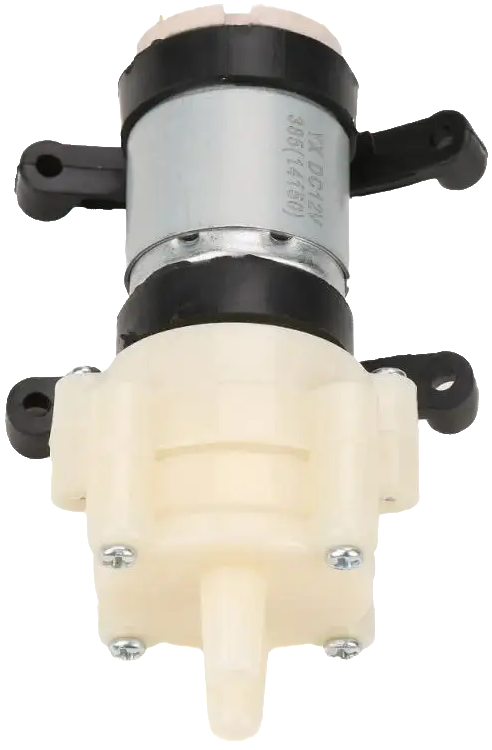
The Mini Diaphragm Water Pump (Manufacturer: HJ, Part ID: HJ) is a compact and efficient pump designed for low-flow water movement applications. It operates using a diaphragm mechanism, which ensures reliable and consistent performance. This pump is widely used in applications such as aquariums, medical devices, small-scale irrigation systems, and DIY electronics projects. Its small size and low power consumption make it an excellent choice for portable and space-constrained designs.
Explore Projects Built with Mini Diaphragm Water Pump
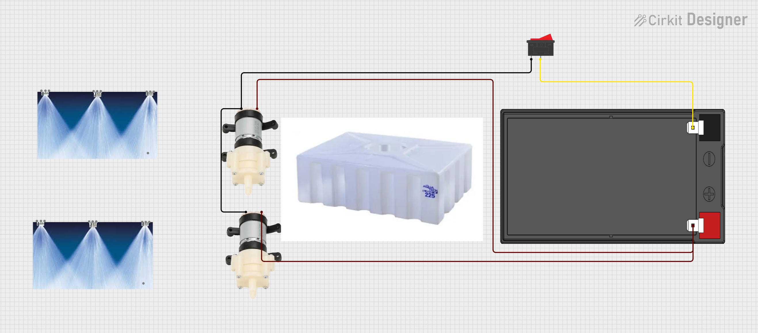
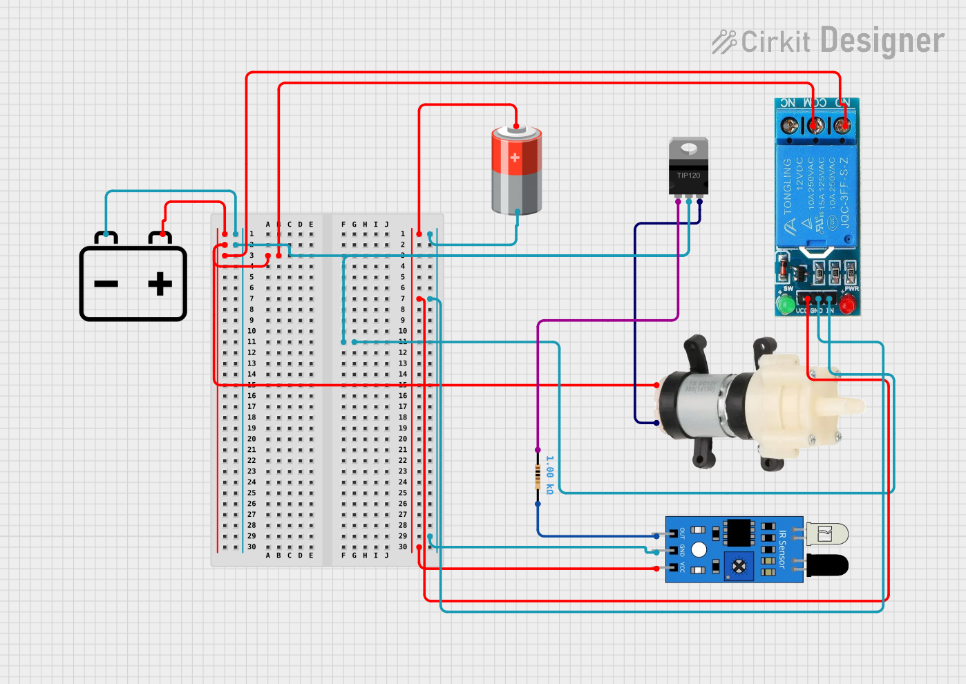
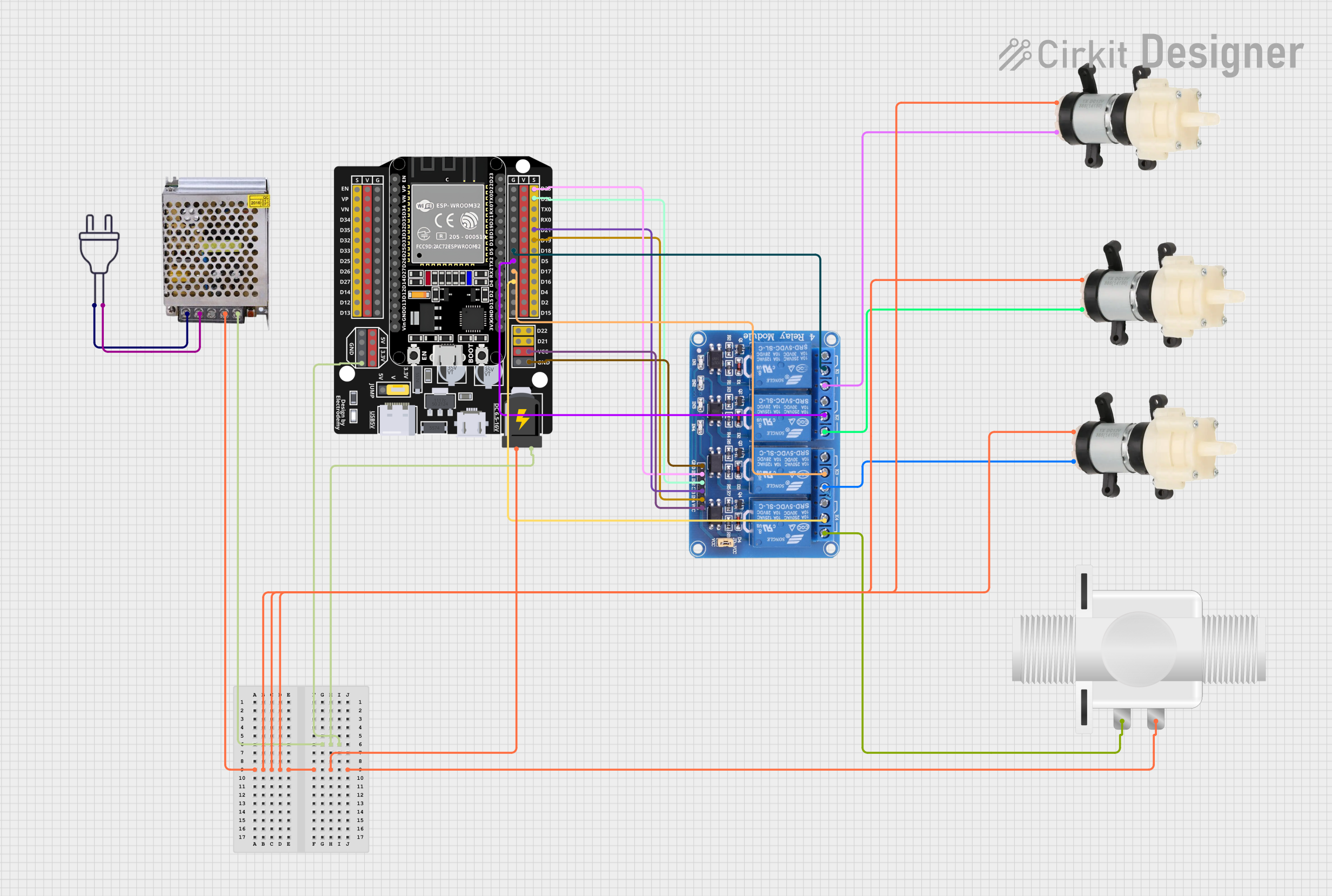
Explore Projects Built with Mini Diaphragm Water Pump
Technical Specifications
Below are the key technical details of the Mini Diaphragm Water Pump:
| Parameter | Value |
|---|---|
| Operating Voltage | 6V to 12V DC |
| Operating Current | 0.5A to 1A |
| Maximum Flow Rate | 1.2 liters per minute (L/min) |
| Maximum Suction Lift | 2 meters |
| Maximum Discharge Head | 3 meters |
| Power Consumption | 6W to 12W |
| Pump Type | Diaphragm |
| Port Size | 6 mm (inlet and outlet) |
| Dimensions | 90 mm x 40 mm x 35 mm |
| Weight | 150 grams |
Pin Configuration and Descriptions
The Mini Diaphragm Water Pump has two electrical terminals for power input:
| Pin | Label | Description |
|---|---|---|
| 1 | V+ | Positive terminal (6V to 12V DC) |
| 2 | GND | Ground terminal |
Usage Instructions
How to Use the Component in a Circuit
- Power Supply: Connect the pump to a DC power source within the operating voltage range (6V to 12V). Ensure the power supply can provide sufficient current (at least 1A).
- Polarity: Connect the positive terminal of the power supply to the V+ pin and the negative terminal to the GND pin.
- Tubing: Attach 6 mm inner diameter tubing to the inlet and outlet ports for water flow. Ensure the tubing is securely fastened to prevent leaks.
- Mounting: Use screws or adhesive to mount the pump securely in your application. Avoid placing the pump in a location where it may be exposed to excessive heat or moisture.
- Control: For automated control, you can use a relay module or a transistor circuit to switch the pump on and off. The pump can also be controlled via a microcontroller like an Arduino.
Important Considerations and Best Practices
- Voltage Range: Do not exceed the specified voltage range (6V to 12V) to avoid damaging the pump.
- Dry Running: Avoid running the pump without water, as this can damage the diaphragm and reduce the pump's lifespan.
- Filtration: Use a pre-filter if the water contains debris or particles to prevent clogging.
- Orientation: Install the pump in a horizontal position for optimal performance.
- Noise Reduction: Use rubber mounts or grommets to minimize vibration and noise during operation.
Example: Controlling the Pump with an Arduino UNO
Below is an example of how to control the Mini Diaphragm Water Pump using an Arduino UNO and a relay module:
// Mini Diaphragm Water Pump Control with Arduino UNO
// This code turns the pump on for 5 seconds and off for 5 seconds in a loop.

const int relayPin = 7; // Pin connected to the relay module

void setup() {
  pinMode(relayPin, OUTPUT); // Set the relay pin as an output
  digitalWrite(relayPin, LOW); // Ensure the pump is off at startup
}

void loop() {
  digitalWrite(relayPin, HIGH); // Turn the pump on
  delay(5000); // Keep the pump on for 5 seconds
  digitalWrite(relayPin, LOW); // Turn the pump off
  delay(5000); // Keep the pump off for 5 seconds
}
Note: Ensure the relay module is rated for the pump's voltage and current. Use an external power supply to power the pump, as the Arduino cannot provide sufficient current.
Troubleshooting and FAQs
Common Issues and Solutions
Pump Does Not Start
- Cause: Insufficient power supply or incorrect wiring.
- Solution: Verify the power supply voltage and current. Check the wiring for proper polarity.
Low Water Flow
- Cause: Blocked tubing or clogged inlet.
- Solution: Inspect and clean the tubing and inlet. Ensure there are no kinks in the tubing.
Excessive Noise
- Cause: Loose mounting or air trapped in the pump.
- Solution: Securely mount the pump and ensure the tubing is properly primed with water.
Pump Overheats
- Cause: Prolonged operation at high voltage or dry running.
- Solution: Operate the pump within the recommended voltage range and avoid running it dry.
FAQs
Q: Can the pump handle liquids other than water?
A: The pump is designed for water. Using other liquids may damage the diaphragm or reduce performance.Q: Can the pump be used for continuous operation?
A: While the pump can run continuously, it is recommended to allow periodic rest to prevent overheating and extend its lifespan.Q: How do I reduce vibration during operation?
A: Use rubber mounts or place the pump on a vibration-dampening surface.Q: Is the pump waterproof?
A: No, the pump is not waterproof. Avoid submerging it in water or exposing it to excessive moisture.
This concludes the documentation for the Mini Diaphragm Water Pump. For further assistance, refer to the manufacturer's datasheet or contact technical support.