
How to Use Water Pump 12 V: Examples, Pinouts, and Specs
 Design with Water Pump 12 V in Cirkit Designer
Introduction
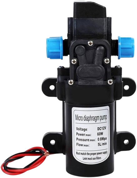
The Water Pump 12V (Manufacturer: PUMP, Part ID: 03) is a compact and efficient device designed for moving water in a variety of applications. It operates on a 12-volt DC power supply and is suitable for tasks such as irrigation, aquarium water circulation, cooling systems, and small-scale water transfer projects. Its compact design and ease of use make it a popular choice for hobbyists and professionals alike.
Explore Projects Built with Water Pump 12 V
 Open Project in Cirkit Designer
 Open Project in Cirkit Designer
 Open Project in Cirkit Designer
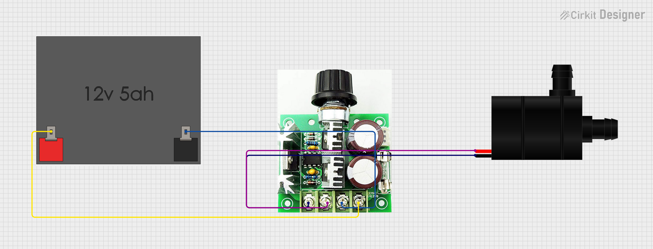 Open Project in Cirkit Designer
Explore Projects Built with Water Pump 12 V
Open Project in Cirkit DesignerOpen Project in Cirkit DesignerOpen Project in Cirkit DesignerOpen Project in Cirkit DesignerCommon Applications
- Irrigation Systems: Ideal for small-scale gardening or hydroponic setups.
- Aquariums: Used for water circulation and filtration.
- Cooling Systems: Helps in liquid cooling for electronics or machinery.
- DIY Projects: Suitable for custom water transfer or pumping applications.
Technical Specifications
Key Technical Details
| Parameter | Specification |
|---|---|
| Operating Voltage | 12V DC |
| Operating Current | 0.5A to 1.5A (depending on load) |
| Power Consumption | 6W to 18W |
| Maximum Flow Rate | 240 liters per hour (L/h) |
| Maximum Lift Height | 3 meters |
| Inlet/Outlet Diameter | 8 mm |
| Material | Plastic (housing), metal (motor) |
| Weight | 200 grams |
| Operating Temperature | 0°C to 50°C |
| Waterproof Rating | IPX4 |
Pin Configuration and Descriptions
The Water Pump 12V typically has two wires for connection:
| Wire Color | Function | Description |
|---|---|---|
| Red | Positive (+) | Connect to the positive terminal of the 12V DC supply. |
| Black | Negative (-) | Connect to the negative terminal (ground). |
Usage Instructions
How to Use the Water Pump in a Circuit
- Power Supply: Ensure you have a stable 12V DC power source capable of supplying at least 1.5A.
- Connections:
- Connect the red wire to the positive terminal of the power supply.
- Connect the black wire to the negative terminal (ground).
- Water Flow:
- Attach hoses to the inlet and outlet ports. Ensure the connections are secure to prevent leaks.
- Prime the pump (if required) by filling the inlet hose with water before powering it on.
- Operation:
- Turn on the power supply to start the pump. Monitor the flow rate and ensure there are no blockages.
Important Considerations and Best Practices
- Polarity: Always connect the wires with the correct polarity to avoid damage.
- Dry Run: Do not operate the pump without water, as this can damage the motor.
- Power Supply: Use a regulated 12V DC power supply to ensure stable operation.
- Mounting: Secure the pump to prevent vibrations or movement during operation.
- Maintenance: Periodically clean the inlet and outlet to prevent clogging.
Example: Using the Water Pump with an Arduino UNO
The Water Pump 12V can be controlled using an Arduino UNO and a relay module. Below is an example circuit and code to turn the pump on and off.
Circuit Diagram
- Connect the pump's red wire to the relay's NO (Normally Open) terminal.
- Connect the pump's black wire to the ground.
- Connect the relay's COM terminal to the 12V power supply's positive terminal.
- Connect the relay's ground and signal pin to the Arduino.
Arduino Code
// Define the relay pin connected to the Arduino
const int relayPin = 7;

void setup() {
  pinMode(relayPin, OUTPUT); // Set the relay pin as an output
  digitalWrite(relayPin, LOW); // Ensure the pump is off initially
}

void loop() {
  digitalWrite(relayPin, HIGH); // Turn the pump on
  delay(5000); // Keep the pump on for 5 seconds
  digitalWrite(relayPin, LOW); // Turn the pump off
  delay(5000); // Keep the pump off for 5 seconds
}
Troubleshooting and FAQs
Common Issues and Solutions
| Issue | Possible Cause | Solution |
|---|---|---|
| Pump does not start | Incorrect wiring or no power | Check connections and ensure 12V power supply is working. |
| Low water flow | Blocked inlet or outlet | Clean the inlet and outlet to remove debris. |
| Pump overheating | Running dry or excessive load | Ensure the pump is submerged or primed with water. |
| Noise during operation | Loose mounting or air in the system | Secure the pump and remove air bubbles. |
FAQs
- Can the pump be used with a battery?
- Yes, the pump can be powered by a 12V battery, such as a lead-acid or lithium-ion battery.
- Is the pump submersible?
- No, this pump is not fully submersible. Only the inlet and outlet hoses should come into contact with water.
- What is the maximum distance the pump can push water?
- The pump can lift water up to 3 meters vertically. Horizontal distance depends on the flow rate and hose diameter.
This concludes the documentation for the Water Pump 12V. For further assistance, refer to the manufacturer's guidelines or contact technical support.