How to Use 12V ~ 5V 5A Buck converter: Examples, Pinouts, and Specs
Introduction
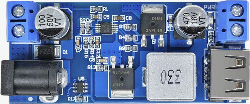
The 12V ~ 5V 5A Buck Converter (Manufacturer: Heemol, Part ID: B0DM9647W2) is a high-efficiency DC-DC step-down voltage regulator. It converts a 12V DC input to a stable 5V DC output, capable of delivering up to 5A of current. This component is widely used in applications where devices operating at 5V need to be powered from a 12V source, such as automotive systems, battery-powered devices, and embedded systems.
Explore Projects Built with 12V ~ 5V 5A Buck converter


Explore Projects Built with 12V ~ 5V 5A Buck converter
Common Applications:
- Powering microcontrollers (e.g., Arduino, Raspberry Pi) from a 12V source.
- Charging USB devices in automotive environments.
- Supplying power to 5V sensors, modules, and peripherals.
- General-purpose voltage regulation in DIY electronics projects.
Technical Specifications
Below are the key technical details of the 12V ~ 5V 5A Buck Converter:
| Parameter | Value |
|---|---|
| Input Voltage Range | 8V to 20V DC |
| Output Voltage | 5V DC |
| Maximum Output Current | 5A |
| Efficiency | Up to 95% |
| Switching Frequency | 150 kHz |
| Operating Temperature | -40°C to +85°C |
| Dimensions | 45mm x 20mm x 14mm |
| Weight | 12g |
Pin Configuration and Descriptions
The buck converter has four main pins or terminals for connection:
| Pin/Terminal | Label | Description |
|---|---|---|
| 1 | VIN | Positive input voltage (8V to 20V DC). |
| 2 | GND | Ground connection for input and output. |
| 3 | VOUT | Positive output voltage (5V DC). |
| 4 | GND | Ground connection for output (shared with input). |
Usage Instructions
How to Use the Buck Converter in a Circuit
Connect the Input Voltage:
- Attach the VIN pin to the positive terminal of your 12V DC power source.
- Connect the GND pin to the ground terminal of your power source.
Connect the Output Voltage:
- Attach the VOUT pin to the positive terminal of the device or circuit requiring 5V.
- Connect the GND pin to the ground terminal of the device or circuit.
Verify Connections:
- Double-check all connections to ensure proper polarity and avoid short circuits.
Power On:
- Turn on the 12V power source. The buck converter will regulate the input voltage to provide a stable 5V output.
Important Considerations and Best Practices
- Heat Dissipation: At high currents (close to 5A), the converter may generate heat. Ensure adequate ventilation or use a heatsink if necessary.
- Input Voltage Range: Do not exceed the specified input voltage range (8V to 20V) to avoid damaging the converter.
- Load Requirements: Ensure the connected load does not draw more than 5A to prevent overloading the converter.
- Filtering Capacitors: For improved stability, you can add external capacitors (e.g., 100µF electrolytic) at the input and output terminals.
Example: Using the Buck Converter with an Arduino UNO
The following example demonstrates how to power an Arduino UNO using the buck converter:
Circuit Connections:
- Connect the VIN pin of the buck converter to a 12V DC power source.
- Connect the GND pin of the buck converter to the ground of the power source.
- Connect the VOUT pin of the buck converter to the 5V pin of the Arduino UNO.
- Connect the GND pin of the buck converter to the GND pin of the Arduino UNO.
Sample Arduino Code:
// Example code to blink an LED connected to pin 13 of the Arduino UNO
// Ensure the Arduino is powered via the 5V pin using the buck converter

void setup() {
  pinMode(13, OUTPUT); // Set pin 13 as an output
}

void loop() {
  digitalWrite(13, HIGH); // Turn the LED on
  delay(1000);            // Wait for 1 second
  digitalWrite(13, LOW);  // Turn the LED off
  delay(1000);            // Wait for 1 second
}
Troubleshooting and FAQs
Common Issues and Solutions
No Output Voltage:
- Cause: Incorrect wiring or insufficient input voltage.
- Solution: Verify that the input voltage is within the 8V to 20V range and check all connections.
Overheating:
- Cause: High current draw or poor ventilation.
- Solution: Reduce the load current or add a heatsink to the converter.
Output Voltage Fluctuations:
- Cause: Insufficient filtering or unstable input voltage.
- Solution: Add external capacitors (e.g., 100µF electrolytic) at the input and output terminals.
Device Not Powering On:
- Cause: Output current insufficient for the connected device.
- Solution: Ensure the device's current requirements do not exceed 5A.
FAQs
Q1: Can I use this buck converter to charge a USB device?
A1: Yes, the converter can be used to charge USB devices, provided the device's current requirements do not exceed 5A.
Q2: What happens if I connect a load that requires more than 5A?
A2: The converter may overheat or shut down to protect itself. Always ensure the load current is within the specified limit.
Q3: Can I use this converter with a 24V input?
A3: No, the maximum input voltage is 20V. Using a 24V input may damage the converter.
Q4: Is the output voltage adjustable?
A4: No, this model provides a fixed 5V output. For adjustable output, consider a different model.
By following this documentation, you can effectively integrate the 12V ~ 5V 5A Buck Converter into your projects and ensure reliable operation.