How to Use 1 Channel USB Powered Relay Module (NL): Examples, Pinouts, and Specs
Introduction
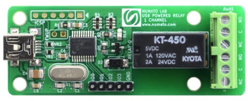
The 1 Channel USB Powered Relay Module (NL), manufactured by Numato Lab (Part ID: usbpowrl002), is a compact and versatile relay module designed for controlling high-voltage devices using a low-voltage USB signal. This module features a single relay channel, making it ideal for simple on/off control applications. It is USB-powered, eliminating the need for an external power supply, and is well-suited for automation, home appliances, and IoT projects.
Explore Projects Built with 1 Channel USB Powered Relay Module (NL)

Explore Projects Built with 1 Channel USB Powered Relay Module (NL)
Common Applications
- Home automation (e.g., controlling lights, fans, or appliances)
- Industrial equipment control
- IoT projects requiring remote switching
- Prototyping and educational purposes
Technical Specifications
Key Technical Details
| Parameter | Value |
|---|---|
| Manufacturer | Numato Lab |
| Part ID | usbpowrl002 |
| Relay Type | SPDT (Single Pole Double Throw) |
| Operating Voltage | 5V DC (via USB) |
| Relay Control Voltage | 5V DC |
| Maximum Switching Voltage | 250V AC / 30V DC |
| Maximum Switching Current | 10A |
| Communication Interface | USB |
| Dimensions | 50mm x 40mm x 20mm |
| Weight | ~30g |
Pin Configuration and Descriptions
The module has a USB interface for power and control, and a terminal block for connecting the load. Below is the pin configuration:
USB Interface
| Pin Name | Description |
|---|---|
| VBUS | 5V DC power supply from USB |
| D+ | USB data line (positive) |
| D- | USB data line (negative) |
| GND | Ground |
Relay Terminal Block
| Pin Name | Description |
|---|---|
| NO | Normally Open contact |
| COM | Common contact |
| NC | Normally Closed contact |
- NO (Normally Open): The circuit is open by default and closes when the relay is activated.
- NC (Normally Closed): The circuit is closed by default and opens when the relay is activated.
- COM (Common): The common terminal for the relay.
Usage Instructions
How to Use the Module in a Circuit
Connect the USB Cable:
- Plug the module into a USB port on your computer or a USB power adapter. This provides both power and control signals.
Connect the Load:
- Identify the type of load you want to control (e.g., a light bulb or motor).
- Connect one terminal of the load to the COM pin and the other terminal to either the NO or NC pin, depending on the desired behavior:
- Use NO if you want the load to turn on when the relay is activated.
- Use NC if you want the load to turn off when the relay is activated.
Control the Relay:
- Use the USB interface to send control signals to the relay. The module can be controlled using simple serial commands from a computer or microcontroller.
Important Considerations and Best Practices
- Power Supply: Ensure the USB port or adapter provides sufficient current (at least 500mA) to power the module and the relay.
- Load Ratings: Do not exceed the maximum switching voltage (250V AC / 30V DC) or current (10A) to avoid damaging the relay.
- Isolation: The relay provides electrical isolation between the control circuit and the load, but additional safety precautions should be taken when working with high voltages.
- Software Control: The module can be controlled using serial commands via a terminal program or custom software. Refer to the manufacturer's documentation for detailed command syntax.
Example: Controlling the Relay with Arduino UNO
The module can be controlled by an Arduino UNO using a USB-to-serial adapter. Below is an example code snippet:
// Example code to control the 1 Channel USB Powered Relay Module (NL)
// using an Arduino UNO. This code sends serial commands to toggle the relay.

void setup() {
  Serial.begin(9600); // Initialize serial communication at 9600 baud
  delay(1000);        // Wait for the relay module to initialize
}

void loop() {
  // Turn the relay ON
  Serial.println("relay on"); // Send command to turn the relay ON
  delay(5000);               // Wait for 5 seconds

  // Turn the relay OFF
  Serial.println("relay off"); // Send command to turn the relay OFF
  delay(5000);                 // Wait for 5 seconds
}
Note: Replace "relay on" and "relay off" with the actual commands specified in the Numato Lab documentation if they differ.
Troubleshooting and FAQs
Common Issues and Solutions
Relay Not Activating:
- Cause: Insufficient power supply or incorrect USB connection.
- Solution: Ensure the USB port provides at least 500mA. Check the USB cable and connection.
Load Not Switching:
- Cause: Incorrect wiring of the load to the relay terminal block.
- Solution: Verify the load is connected to the correct pins (COM and NO/NC) based on the desired behavior.
Serial Commands Not Working:
- Cause: Incorrect baud rate or command syntax.
- Solution: Ensure the baud rate is set to 9600 and the commands match the manufacturer's documentation.
Overheating:
- Cause: Exceeding the relay's maximum current or voltage ratings.
- Solution: Check the load specifications and ensure they are within the relay's limits.
FAQs
Q: Can I use this module with a Raspberry Pi?
A: Yes, the module can be controlled by a Raspberry Pi using its USB interface. Use Python's serial library to send commands.
Q: Is the relay module safe for high-voltage applications?
A: The relay is rated for up to 250V AC and 10A, but proper safety precautions must be taken when working with high voltages.
Q: Can I control multiple modules simultaneously?
A: Yes, multiple modules can be connected to different USB ports and controlled independently.
Q: Does the module require any drivers?
A: Most operating systems recognize the module as a standard USB device. If not, refer to the Numato Lab website for driver downloads.
Q: What is the lifespan of the relay?
A: The relay is rated for approximately 100,000 operations under normal conditions.