
How to Use Motor: Examples, Pinouts, and Specs
 Design with Motor in Cirkit Designer
Introduction
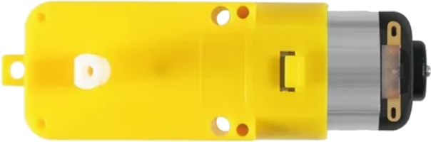
A motor is a device that converts electrical energy into mechanical energy. It is a fundamental component in countless applications, ranging from industrial machinery to household appliances, robotics, and automotive systems. Motors are available in various types, such as DC motors, AC motors, and stepper motors, each suited for specific tasks and performance requirements.
Common applications of motors include:
- Driving conveyor belts, fans, and pumps in industrial settings
- Powering household appliances like washing machines and vacuum cleaners
- Enabling motion in robotics and automated systems
- Propelling vehicles, such as electric cars and drones
Explore Projects Built with Motor
 Open Project in Cirkit Designer
 Open Project in Cirkit Designer
 Open Project in Cirkit Designer
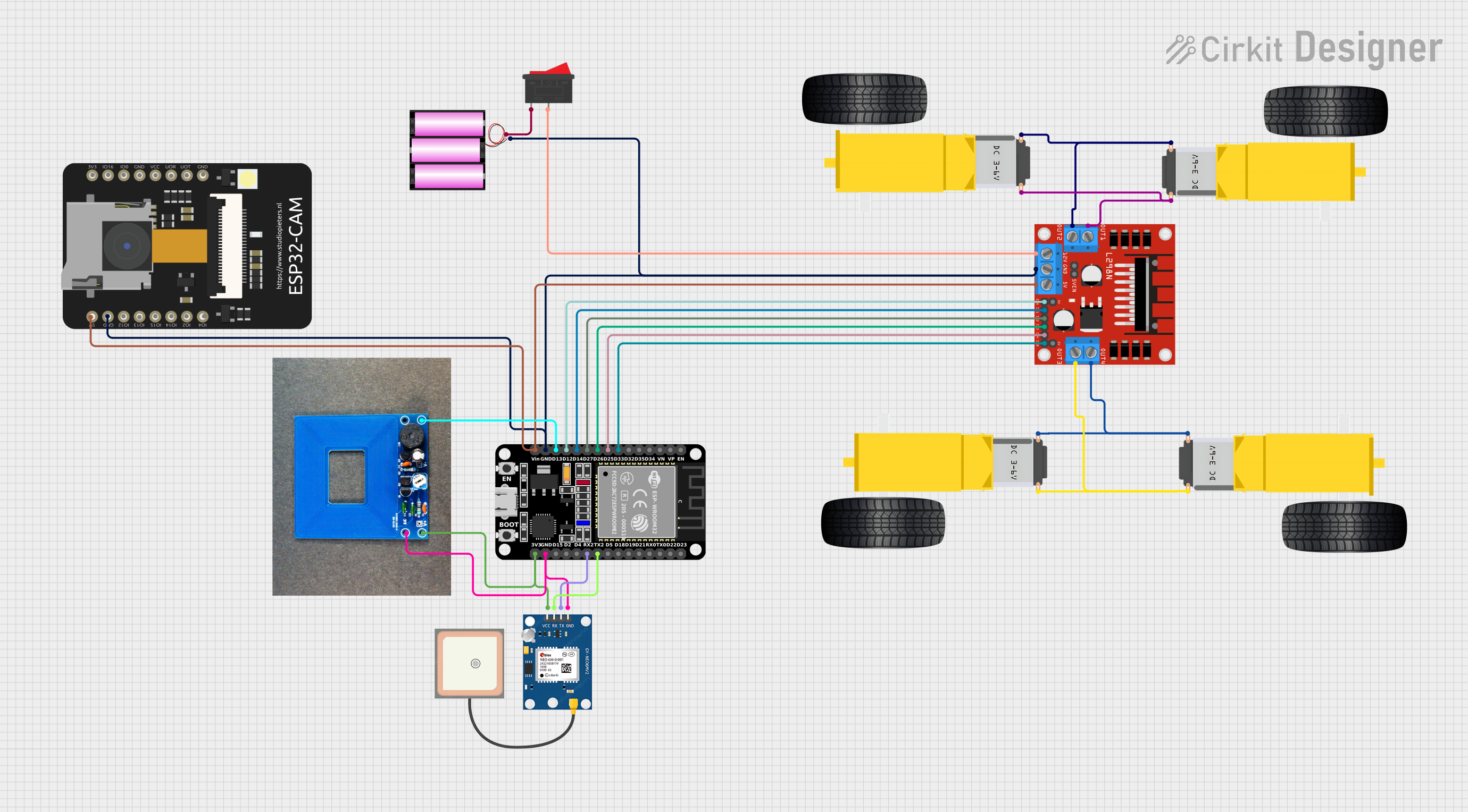 Open Project in Cirkit Designer
Explore Projects Built with Motor
Open Project in Cirkit DesignerOpen Project in Cirkit DesignerOpen Project in Cirkit DesignerOpen Project in Cirkit DesignerTechnical Specifications
The specifications of a motor can vary depending on its type and intended use. Below are general technical details for a typical DC motor:
General Specifications
| Parameter | Value |
|---|---|
| Operating Voltage | 3V to 24V |
| Rated Current | 100mA to 2A (depending on size) |
| Stall Current | Up to 10A |
| Speed | 1000 to 10,000 RPM |
| Torque | 0.1 to 10 Nm |
| Power Output | 0.1W to 100W |
Pin Configuration (for a basic DC motor)
| Pin Name | Description |
|---|---|
| Positive (+) | Connect to the positive terminal of the power supply |
| Negative (-) | Connect to the negative terminal of the power supply |
For motors with additional features (e.g., encoders or stepper motors), refer to the specific datasheet for pin details.
Usage Instructions
How to Use a Motor in a Circuit
- Power Supply: Ensure the motor is powered by a voltage source within its operating range. Exceeding the voltage rating can damage the motor.
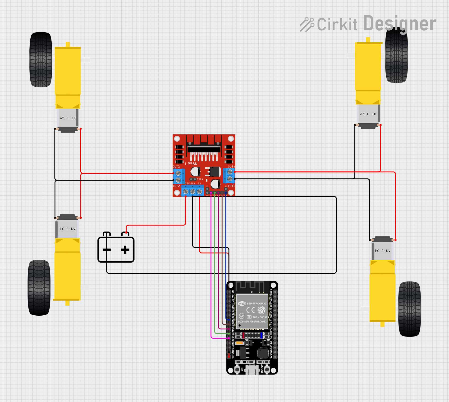
- Motor Driver: Use a motor driver (e.g., L298N or L293D) to control the motor. Directly connecting a motor to a microcontroller is not recommended due to high current requirements.
- Connections:
- Connect the motor's positive and negative terminals to the motor driver outputs.
- Connect the motor driver inputs to the control signals from a microcontroller or other control circuit.
- Control: Use Pulse Width Modulation (PWM) to control the motor's speed and direction.
Example: Controlling a DC Motor with Arduino UNO
Below is an example of how to control a DC motor using an Arduino UNO and an L298N motor driver.
// Arduino code to control a DC motor using PWM and an L298N motor driver

// Define motor control pins
const int motorPin1 = 9; // IN1 on L298N
const int motorPin2 = 10; // IN2 on L298N
const int enablePin = 11; // ENA on L298N

void setup() {
  // Set motor control pins as outputs
  pinMode(motorPin1, OUTPUT);
  pinMode(motorPin2, OUTPUT);
  pinMode(enablePin, OUTPUT);

  // Initialize motor in stopped state
  digitalWrite(motorPin1, LOW);
  digitalWrite(motorPin2, LOW);
  analogWrite(enablePin, 0); // Set speed to 0
}

void loop() {
  // Rotate motor forward at 50% speed
  digitalWrite(motorPin1, HIGH);
  digitalWrite(motorPin2, LOW);
  analogWrite(enablePin, 128); // 50% duty cycle (0-255)

  delay(2000); // Run for 2 seconds

  // Rotate motor backward at 75% speed
  digitalWrite(motorPin1, LOW);
  digitalWrite(motorPin2, HIGH);
  analogWrite(enablePin, 192); // 75% duty cycle

  delay(2000); // Run for 2 seconds

  // Stop the motor
  digitalWrite(motorPin1, LOW);
  digitalWrite(motorPin2, LOW);
  analogWrite(enablePin, 0); // Set speed to 0

  delay(2000); // Wait for 2 seconds
}
Important Considerations
- Current Handling: Ensure the motor driver can handle the motor's stall current to avoid damage.
- Heat Dissipation: Motors and drivers may generate heat during operation. Use heat sinks or cooling mechanisms if necessary.
- Power Supply: Use a separate power supply for the motor to prevent voltage drops affecting the microcontroller.
Troubleshooting and FAQs
Common Issues
Motor Does Not Spin:
- Check the power supply voltage and connections.
- Verify that the motor driver is receiving control signals.
- Ensure the motor is not overloaded or stalled.
Motor Spins in the Wrong Direction:
- Reverse the connections to the motor terminals or adjust the control signals.
Motor Overheats:
- Reduce the load on the motor.
- Check for proper ventilation and cooling.
Noisy Operation:
- Inspect for loose connections or mechanical misalignment.
- Use capacitors across the motor terminals to reduce electrical noise.
FAQs
Q: Can I connect a motor directly to an Arduino?
A: No, motors typically require more current than an Arduino can supply. Always use a motor driver or relay module.
Q: How do I control the speed of a motor?
A: Use PWM signals to adjust the motor's speed. Most motor drivers support PWM input.
Q: What is stall current, and why is it important?
A: Stall current is the maximum current a motor draws when it is not rotating. Ensure your motor driver and power supply can handle this current to avoid damage.
Q: Can I use the same power supply for the motor and microcontroller?
A: It is possible, but not recommended. Motors can cause voltage fluctuations that may interfere with the microcontroller's operation. Use separate power supplies or proper decoupling techniques.
By following this documentation, you can effectively integrate and troubleshoot motors in your projects.