
How to Use AD725: Examples, Pinouts, and Specs
 Design with AD725 in Cirkit Designer
Introduction
The AD725, manufactured by Analog Devices, is a high-performance video Digital-to-Analog Converter (DAC) designed for converting digital video signals into analog format. It is widely used in applications requiring high-quality video output, such as video processing systems, gaming consoles, and multimedia devices. The AD725 supports NTSC and PAL video standards and includes features like color space conversion and gamma correction, making it ideal for professional and consumer-grade video applications.
Explore Projects Built with AD725
 Open Project in Cirkit Designer
 Open Project in Cirkit Designer
 Open Project in Cirkit Designer
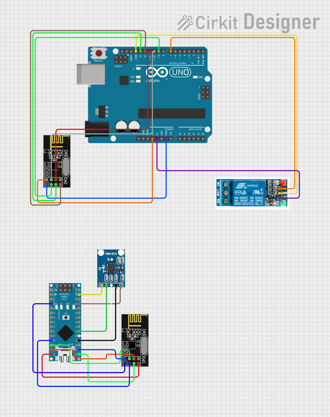 Open Project in Cirkit Designer
Explore Projects Built with AD725
Open Project in Cirkit DesignerOpen Project in Cirkit DesignerOpen Project in Cirkit DesignerOpen Project in Cirkit DesignerCommon Applications
- Video signal conversion for NTSC and PAL standards
- Gaming consoles and multimedia devices
- Set-top boxes and video processing systems
- Video overlay and display systems
- Consumer electronics requiring composite or S-Video output
Technical Specifications
Key Technical Details
| Parameter | Value |
|---|---|
| Manufacturer | Analog Devices |
| Part Number | AD725 |
| Supply Voltage (Vcc) | 4.75V to 5.25V |
| Power Consumption | 50 mW (typical) |
| Input Signal Format | Digital RGB or YUV |
| Output Signal Format | Composite Video (CVBS) and S-Video |
| Supported Standards | NTSC, PAL |
| Operating Temperature Range | 0°C to +70°C |
| Package Type | 16-pin SOIC or PDIP |
Pin Configuration and Descriptions
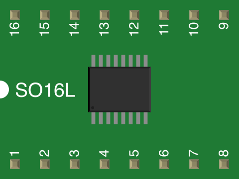
The AD725 is available in a 16-pin package. Below is the pin configuration and description:
| Pin Number | Pin Name | Description |
|---|---|---|
| 1 | RIN | Red input signal (digital) |
| 2 | GIN | Green input signal (digital) |
| 3 | BIN | Blue input signal (digital) |
| 4 | GND | Ground connection |
| 5 | VREF | Voltage reference input |
| 6 | COMP | Compensation pin for internal circuitry |
| 7 | LUMA | Luminance (Y) output for S-Video |
| 8 | CHROMA | Chrominance (C) output for S-Video |
| 9 | CVBS | Composite video output |
| 10 | GND | Ground connection |
| 11 | VCC | Positive supply voltage |
| 12 | FSC | Frequency subcarrier input for NTSC/PAL encoding |
| 13 | PAL/NTSC | Selects video standard: High = PAL, Low = NTSC |
| 14 | ENABLE | Enables the DAC operation |
| 15 | TEST | Test pin (leave unconnected in normal operation) |
| 16 | GND | Ground connection |
Usage Instructions
How to Use the AD725 in a Circuit
- Power Supply: Connect the VCC pin to a regulated 5V power supply and the GND pins to ground. Ensure proper decoupling capacitors (e.g., 0.1 µF) are placed close to the VCC pin to minimize noise.
- Input Signals: Provide digital RGB or YUV signals to the RIN, GIN, and BIN pins. Ensure the input signals are within the specified voltage levels.
- Video Standard Selection: Use the PAL/NTSC pin to select the desired video standard. Connect it to VCC for PAL or GND for NTSC.
- Output Connections:
- For composite video output, connect the CVBS pin to the desired output device (e.g., TV or monitor).
- For S-Video output, connect the LUMA and CHROMA pins to the corresponding inputs on the display device.
- Frequency Subcarrier: Provide a stable frequency subcarrier signal to the FSC pin for proper encoding of NTSC or PAL signals.
- Enable Operation: Ensure the ENABLE pin is set high to activate the DAC.
Important Considerations and Best Practices
- Use proper shielding and grounding techniques to minimize noise and interference in video signals.
- Ensure the frequency subcarrier signal is accurate and stable for proper color encoding.
- Avoid leaving unused input pins floating; connect them to ground if not in use.
- Use high-quality cables and connectors for video output to maintain signal integrity.
Example: Connecting AD725 to an Arduino UNO
The AD725 can be interfaced with an Arduino UNO to generate composite video output. Below is an example code snippet for generating a simple NTSC video signal:
// Example code for generating NTSC video signal using Arduino UNO
// Note: This is a basic example and may require additional circuitry
// for proper signal conditioning and timing.

#define R_PIN 9  // Red signal pin
#define G_PIN 10 // Green signal pin
#define B_PIN 11 // Blue signal pin

void setup() {
  pinMode(R_PIN, OUTPUT);
  pinMode(G_PIN, OUTPUT);
  pinMode(B_PIN, OUTPUT);
}

void loop() {
  // Generate a simple color pattern
  digitalWrite(R_PIN, HIGH); // Red signal high
  digitalWrite(G_PIN, LOW);  // Green signal low
  digitalWrite(B_PIN, LOW);  // Blue signal low
  delay(500);                // Hold for 500ms

  digitalWrite(R_PIN, LOW);  // Red signal low
  digitalWrite(G_PIN, HIGH); // Green signal high
  digitalWrite(B_PIN, LOW);  // Blue signal low
  delay(500);                // Hold for 500ms

  digitalWrite(R_PIN, LOW);  // Red signal low
  digitalWrite(G_PIN, LOW);  // Green signal low
  digitalWrite(B_PIN, HIGH); // Blue signal high
  delay(500);                // Hold for 500ms
}
Troubleshooting and FAQs
Common Issues and Solutions
No Video Output:
- Ensure the ENABLE pin is set high.
- Verify the power supply voltage is within the specified range (4.75V to 5.25V).
- Check the input signals for proper voltage levels and timing.
Distorted or Noisy Video:
- Verify the frequency subcarrier signal is stable and accurate.
- Check for proper grounding and shielding in the circuit.
- Use high-quality cables and connectors for video output.
Incorrect Color Encoding:
- Ensure the PAL/NTSC pin is set correctly for the desired video standard.
- Verify the input signals are properly formatted (RGB or YUV).
FAQs
Q: Can the AD725 be used with a 3.3V microcontroller?
A: The AD725 requires a 5V power supply for operation. If using a 3.3V microcontroller, level shifters may be needed to interface the digital signals.
Q: What is the maximum resolution supported by the AD725?
A: The AD725 is designed for standard-definition video applications and supports resolutions up to 720x576 (PAL) or 720x480 (NTSC).
Q: Can the AD725 output both composite and S-Video simultaneously?
A: Yes, the AD725 can output both composite video (CVBS) and S-Video (LUMA and CHROMA) simultaneously.
Q: Is an external oscillator required for the FSC pin?
A: Yes, a stable external oscillator is required to provide the frequency subcarrier signal for proper NTSC or PAL encoding.