How to Use SIM 7020c: Examples, Pinouts, and Specs
Introduction
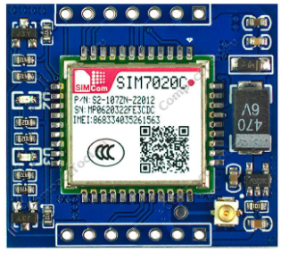
The SIM 7020c is a low-power cellular module manufactured by SIMCom Wireless Solutions (Part ID: S2-107GX-Z2017). It is specifically designed for IoT (Internet of Things) applications, supporting LTE-M and NB-IoT connectivity. This module is ideal for applications requiring low power consumption, reliable connectivity, and compact design.
With its built-in GPS positioning capabilities and multiple interfaces, the SIM 7020c is highly versatile and can be easily integrated into various embedded systems. It is widely used in smart metering, asset tracking, industrial automation, and environmental monitoring.
Explore Projects Built with SIM 7020c


Explore Projects Built with SIM 7020c
Technical Specifications
Key Technical Details
| Parameter | Specification |
|---|---|
| Cellular Technology | LTE-M (Cat-M1), NB-IoT (Cat-NB1) |
| Frequency Bands | LTE B1/B2/B3/B4/B5/B8/B12/B13/B18/B19/B20/B25/B28/B66/B85 |
| Data Rate | LTE-M: Uplink 375 kbps, Downlink 300 kbps NB-IoT: Uplink 66 kbps, Downlink 26 kbps |
| Power Supply Voltage | 3.1V to 4.2V (Typical: 3.8V) |
| Power Consumption | Idle: ~3.2mA Active: ~15mA (LTE-M), ~10mA (NB-IoT) |
| Operating Temperature | -40°C to +85°C |
| Positioning | GPS, GLONASS, BeiDou |
| Dimensions | 17.6mm x 15.7mm x 2.3mm |
| Interfaces | UART, GPIO, ADC, I2C, SPI |
| Antenna Interface | 50Ω impedance, supports external antenna |
| Certifications | CE, FCC, RoHS, REACH |
Pin Configuration and Descriptions
The SIM 7020c module has a total of 42 pins. Below is a summary of the key pins:
| Pin Number | Pin Name | Description |
|---|---|---|
| 1 | VCC | Power supply input (3.1V to 4.2V) |
| 2 | GND | Ground connection |
| 3 | TXD | UART Transmit Data |
| 4 | RXD | UART Receive Data |
| 5 | RESET | Reset pin (active low) |
| 6 | PWRKEY | Power-on key (active low, hold for 1 second to power on/off) |
| 7 | NETLIGHT | Network status indicator (blinks to indicate connection status) |
| 8 | ADC_IN | Analog-to-Digital Converter input |
| 9 | GPIO1 | General-purpose input/output |
| 10 | GPIO2 | General-purpose input/output |
| 11 | I2C_SCL | I2C clock line |
| 12 | I2C_SDA | I2C data line |
| 13 | SPI_CLK | SPI clock line |
| 14 | SPI_MOSI | SPI Master Out Slave In |
| 15 | SPI_MISO | SPI Master In Slave Out |
| 16 | SPI_CS | SPI Chip Select |
| 17 | ANT | Antenna interface (50Ω impedance) |
For a complete pinout, refer to the official SIMCom datasheet.
Usage Instructions
How to Use the SIM 7020c in a Circuit
- Power Supply: Connect the VCC pin to a stable power source (3.8V typical) and GND to ground. Ensure the power supply can handle peak currents of up to 500mA.
- Power On: Use the PWRKEY pin to turn on the module. Pull the pin low for at least 1 second and then release it.
- UART Communication: Connect the TXD and RXD pins to a microcontroller or PC for serial communication. Use a baud rate of 9600 bps (default).
- Antenna Connection: Attach an external antenna to the ANT pin for optimal signal reception.
- Network Configuration: Use AT commands to configure the module for LTE-M or NB-IoT connectivity. For example:
AT+CGDCONT=1,"IP","<APN>"to set the Access Point Name (APN).AT+CFUN=1to enable full functionality.
- Data Transmission: Use AT commands like
AT+NSOSTto send data andAT+NSORFto receive data.
Important Considerations and Best Practices
- Power Stability: Ensure the power supply is stable and capable of handling the module's peak current requirements.
- Antenna Placement: Place the antenna away from noise sources and ensure it is properly matched to the module's impedance.
- Firmware Updates: Regularly check for firmware updates from SIMCom to ensure compatibility and performance.
- ESD Protection: Use proper ESD protection measures when handling the module to prevent damage.
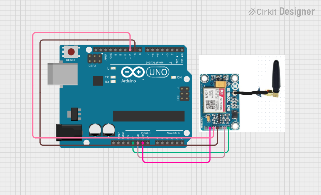
Example: Connecting SIM 7020c to Arduino UNO
Below is an example of how to interface the SIM 7020c with an Arduino UNO for basic communication:
Circuit Connections
| SIM 7020c Pin | Arduino UNO Pin |
|---|---|
| VCC | 3.3V |
| GND | GND |
| TXD | Pin 10 (RX) |
| RXD | Pin 11 (TX) |
| PWRKEY | Digital Pin 7 |
Arduino Code
#include <SoftwareSerial.h>

// Define RX and TX pins for SoftwareSerial
SoftwareSerial sim7020c(10, 11); // RX = Pin 10, TX = Pin 11

#define PWRKEY 7 // Power key pin

void setup() {
  pinMode(PWRKEY, OUTPUT);
  digitalWrite(PWRKEY, HIGH); // Set PWRKEY high initially

  // Start serial communication
  Serial.begin(9600); // For debugging
  sim7020c.begin(9600); // For SIM 7020c communication

  // Power on the SIM 7020c module
  digitalWrite(PWRKEY, LOW); // Pull PWRKEY low
  delay(1000); // Hold for 1 second
  digitalWrite(PWRKEY, HIGH); // Release PWRKEY
  delay(5000); // Wait for the module to initialize

  Serial.println("SIM 7020c Initialized");
}

void loop() {
  // Send an AT command to check module status
  sim7020c.println("AT");
  delay(1000);

  // Read and print the response
  while (sim7020c.available()) {
    String response = sim7020c.readString();
    Serial.println(response);
  }

  delay(5000); // Wait before sending the next command
}
Troubleshooting and FAQs
Common Issues and Solutions
Module Not Powering On
- Ensure the PWRKEY pin is pulled low for at least 1 second during power-on.
- Verify the power supply voltage is within the 3.1V to 4.2V range.
No Network Connection
- Check the antenna connection and placement.
- Verify the APN settings using the
AT+CGDCONTcommand. - Ensure the module is in an area with LTE-M or NB-IoT coverage.
No Response to AT Commands
- Confirm the UART connections (TXD and RXD) are correct.
- Check the baud rate settings (default is 9600 bps).
- Ensure the module is powered on and initialized.
High Power Consumption
- Verify the module is in idle mode when not transmitting data.
- Use the
AT+CSCLK=1command to enable sleep mode.
FAQs
Q: Can the SIM 7020c operate on 2G networks?
A: No, the SIM 7020c only supports LTE-M and NB-IoT networks.Q: How do I update the firmware?
A: Firmware updates can be performed using the SIMCom firmware update tool via UART.Q: What is the maximum data rate for NB-IoT?
A: The maximum uplink data rate is 66 kbps, and the maximum downlink data rate is 26 kbps.Q: Can I use the SIM 7020c for GPS tracking?
A: Yes, the module supports GPS, GLONASS, and BeiDou for positioning.
For further assistance, refer to the official SIMCom documentation or contact technical support.