How to Use Arduino GIGA R1: Examples, Pinouts, and Specs
Introduction
The Arduino GIGA R1 WiFi is a high-performance microcontroller board designed for advanced projects that require significant processing power and connectivity. Powered by a 32-bit ARM Cortex-M7 processor, it offers exceptional computational capabilities, making it ideal for applications such as robotics, IoT, machine learning, and multimedia projects. The board also features integrated Wi-Fi and Bluetooth, enabling seamless wireless communication.
Explore Projects Built with Arduino GIGA R1
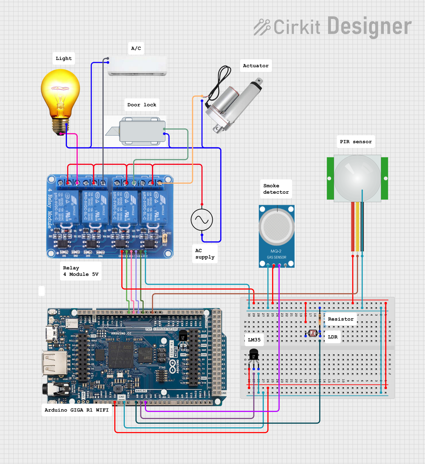
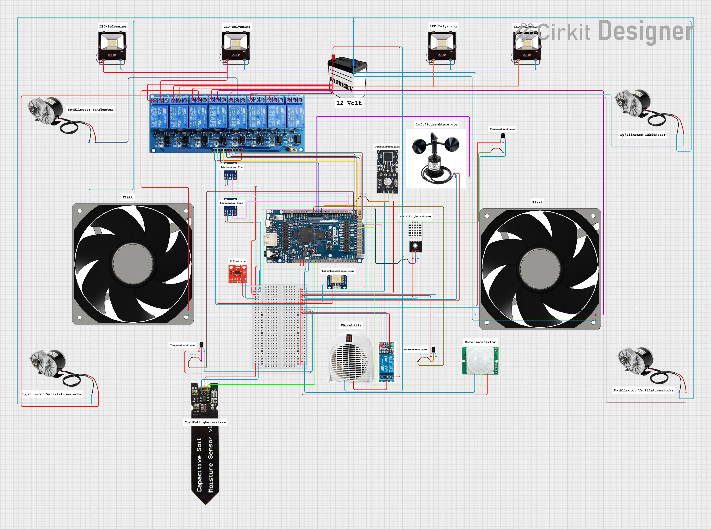
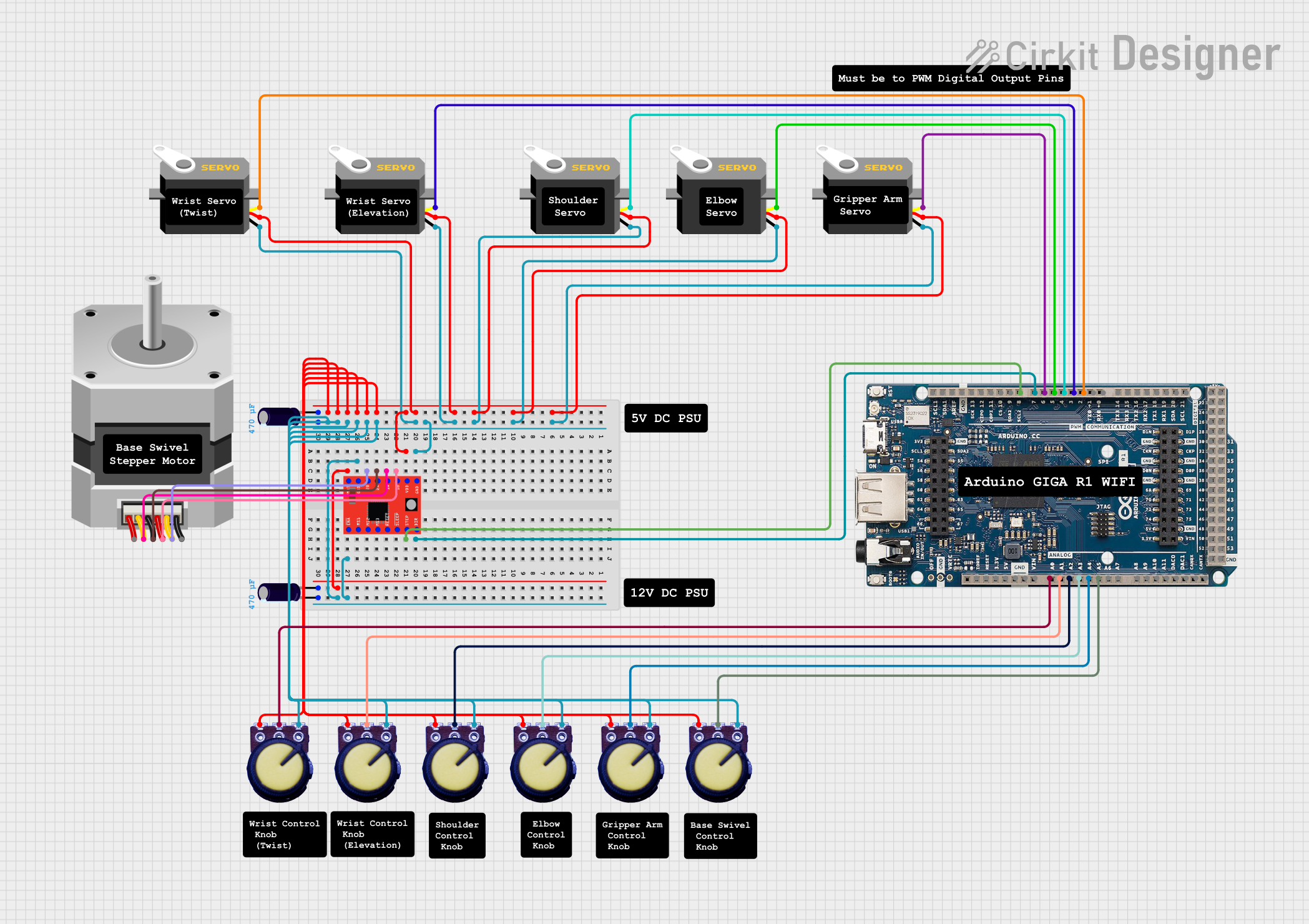
Explore Projects Built with Arduino GIGA R1
Common Applications and Use Cases
- Robotics and automation systems
- IoT (Internet of Things) devices and smart home applications
- Machine learning and AI-based projects
- Multimedia processing, such as audio and video applications
- High-speed data acquisition and processing
- Prototyping for industrial and commercial systems
Technical Specifications
The Arduino GIGA R1 WiFi is packed with features to support a wide range of applications. Below are its key technical specifications:
Key Technical Details
| Specification | Value |
|---|---|
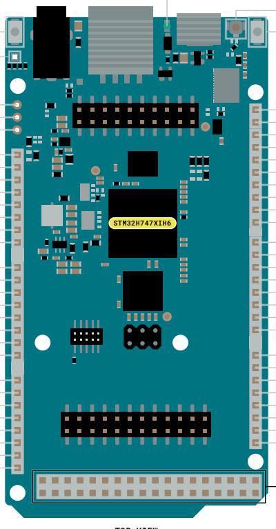
| Microcontroller | STM32H747XI (ARM Cortex-M7 @ 480 MHz + ARM Cortex-M4 @ 240 MHz) |
| Operating Voltage | 3.3V |
| Input Voltage (VIN) | 7-12V |
| Digital I/O Pins | 76 (12 PWM outputs) |
| Analog Input Pins | 12 |
| Analog Output Pins | 2 (DAC) |
| Flash Memory | 8 MB |
| SRAM | 1 MB |
| EEPROM | None |
| Wi-Fi | Integrated (802.11 b/g/n) |
| Bluetooth | BLE 5.1 |
| USB Ports | USB-C (programming and power) |
| Communication Interfaces | UART, I2C, SPI, CAN, Ethernet |
| Dimensions | 102 x 25 mm |
Pin Configuration and Descriptions
The Arduino GIGA R1 WiFi features a rich set of pins for various functionalities. Below is a summary of the pin configuration:
Digital and Analog Pins
| Pin Number | Functionality | Description |
|---|---|---|
| D0-D13 | Digital I/O | General-purpose digital input/output pins |
| A0-A11 | Analog Input | Analog input pins (12-bit resolution) |
| DAC0, DAC1 | Analog Output | Digital-to-Analog Converter pins |
Communication Pins
| Pin Number | Functionality | Description |
|---|---|---|
| TX, RX | UART Communication | Serial communication pins |
| SDA, SCL | I2C Communication | I2C data and clock lines |
| MOSI, MISO, SCK | SPI Communication | SPI data and clock lines |
Power Pins
| Pin Number | Functionality | Description |
|---|---|---|
| VIN | Input Voltage | External power input (7-12V) |
| 3.3V | Power Output | 3.3V regulated output |
| 5V | Power Output | 5V regulated output |
| GND | Ground | Ground pins |
Usage Instructions
The Arduino GIGA R1 WiFi is versatile and easy to use. Below are the steps and best practices for integrating it into your projects.
How to Use the Component in a Circuit
Powering the Board:
- Connect the board to your computer via the USB-C port for programming and power.
- Alternatively, use the VIN pin to supply 7-12V from an external power source.
Programming the Board:
- Install the Arduino IDE (version 2.0 or later) and add the GIGA R1 WiFi board via the Board Manager.
- Select the correct board and port in the IDE, then upload your code.
Connecting Peripherals:
- Use the digital and analog pins to connect sensors, actuators, and other peripherals.
- For wireless communication, configure the Wi-Fi or Bluetooth module using the appropriate libraries.
Example Circuit:
- Connect an LED to pin D13 with a 220-ohm resistor in series.
- Use the following code to blink the LED:
// Example code to blink an LED on pin D13
void setup() {
  pinMode(13, OUTPUT); // Set pin D13 as an output
}

void loop() {
  digitalWrite(13, HIGH); // Turn the LED on
  delay(1000);            // Wait for 1 second
  digitalWrite(13, LOW);  // Turn the LED off
  delay(1000);            // Wait for 1 second
}
Important Considerations and Best Practices
- Voltage Levels: The board operates at 3.3V logic levels. Ensure connected peripherals are compatible or use level shifters.
- Wi-Fi and Bluetooth: Use the
WiFiandBluetoothSeriallibraries for wireless communication. Avoid using both simultaneously for optimal performance. - Power Supply: When using power-hungry peripherals, ensure the power source can supply sufficient current.
Arduino UNO Compatibility
The Arduino GIGA R1 WiFi is compatible with many Arduino UNO shields. However, ensure the shield operates at 3.3V logic levels to avoid damage.
Troubleshooting and FAQs
Common Issues and Solutions
The board is not detected by the Arduino IDE:
- Ensure the correct USB driver is installed.
- Check that the USB cable is functional and supports data transfer.
- Verify that the correct board and port are selected in the IDE.
Wi-Fi or Bluetooth is not working:
- Ensure the correct libraries (
WiFiorBluetoothSerial) are included in your code. - Check that the board is within range of the Wi-Fi network or Bluetooth device.
- Ensure the correct libraries (
Code upload fails:
- Press the reset button on the board and try uploading again.
- Ensure no other application is using the COM port.
Peripherals are not responding:
- Double-check the wiring and connections.
- Verify that the peripherals are compatible with 3.3V logic levels.
FAQs
Q: Can I use the Arduino GIGA R1 WiFi for battery-powered projects?
A: Yes, you can power the board using a battery connected to the VIN pin. Ensure the battery voltage is within the 7-12V range.
Q: Is the board compatible with Arduino libraries?
A: Most Arduino libraries are compatible with the GIGA R1 WiFi. However, some libraries may require modifications for the ARM Cortex-M7 architecture.
Q: Can I use the board for real-time applications?
A: Yes, the dual-core architecture (Cortex-M7 and Cortex-M4) allows for real-time processing and multitasking.
Q: How do I update the firmware?
A: Firmware updates can be performed via the Arduino IDE or the STM32CubeProgrammer tool.
By following this documentation, you can effectively utilize the Arduino GIGA R1 WiFi for a wide range of advanced projects.