Cirkit Designer Logo
Cirkit Designer
Your all-in-one circuit design IDE
Home / 
Component Documentation

How to Use MCCB 3P: Examples, Pinouts, and Specs

Image of MCCB 3P
Cirkit Designer LogoDesign with MCCB 3P in Cirkit Designer

Introduction

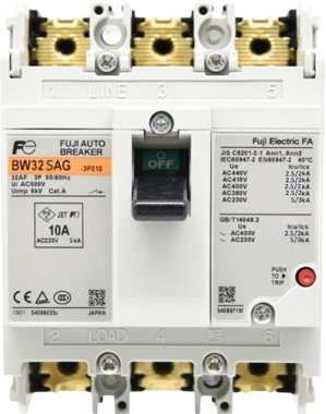
The Fuji BW32-SAG is a three-pole Molded Case Circuit Breaker (MCCB) designed to provide reliable protection for electrical circuits. It safeguards against overloads, short circuits, and other electrical faults, ensuring the safety and longevity of connected equipment. This MCCB is suitable for both industrial and commercial applications, offering manual operation and reset functionality.

Explore Projects Built with MCCB 3P

Use Cirkit Designer to design, explore, and prototype these projects online. Some projects support real-time simulation. Click "Open Project" to start designing instantly!
Industrial Power Distribution and Safety Control System
Image of Control Diagram: A project utilizing MCCB 3P in a practical application
This circuit is designed for power distribution and safety control in an industrial setting. It features a main isolator and circuit breaker for power management, multiple PSUs for 5V, 12V, and 24V outputs, and a safety relay system that interfaces with E-stop buttons and a start switch to control a main contactor, ensuring safe operation and emergency power cut-off capabilities.
Cirkit Designer LogoOpen Project in Cirkit Designer
Solar-Powered Home Energy System with Automatic Transfer Switch and Battery Backup
Image of CDP: A project utilizing MCCB 3P in a practical application
This circuit is a solar power system with an automatic transfer switch (ATS) that manages power from both a solar panel and an AC supply. The solar panel charges a battery through a solar charge controller, and the power inverter converts the stored DC power to AC, which is then distributed through an MCB to a socket. The ATS ensures seamless switching between solar and AC power sources.
Cirkit Designer LogoOpen Project in Cirkit Designer
Battery-Powered 18650 Li-ion Charger with USB Output and Adjustable Voltage Regulator
Image of Breadboard: A project utilizing MCCB 3P in a practical application
This circuit is a battery management and power supply system that uses three 3.7V batteries connected to a 3S 10A Li-ion 18650 Charger Protection Board Module for balanced charging and protection. The system includes a TP4056 Battery Charging Protection Module for additional charging safety, a Step Up Boost Power Converter to regulate and boost the voltage, and a USB regulator to provide a stable 5V output, controlled by a push switch.
Cirkit Designer LogoOpen Project in Cirkit Designer
Flush Switch Controlled Lamp Circuit with AC Power Supply and MCB Protection
Image of LAMP CONTROLE WITH MCB: A project utilizing MCCB 3P in a practical application
This circuit is designed to control a lamp using a flush switch and is protected by two MCBs (Miniature Circuit Breakers). The AC supply is connected to the input of the first MCB, whose output is connected to the flush switch. The flush switch then controls the power to the lamp, with the second MCB placed in the neutral line for additional safety.
Cirkit Designer LogoOpen Project in Cirkit Designer

Explore Projects Built with MCCB 3P

Use Cirkit Designer to design, explore, and prototype these projects online. Some projects support real-time simulation. Click "Open Project" to start designing instantly!
Image of Control Diagram: A project utilizing MCCB 3P in a practical application
Industrial Power Distribution and Safety Control System
This circuit is designed for power distribution and safety control in an industrial setting. It features a main isolator and circuit breaker for power management, multiple PSUs for 5V, 12V, and 24V outputs, and a safety relay system that interfaces with E-stop buttons and a start switch to control a main contactor, ensuring safe operation and emergency power cut-off capabilities.
Cirkit Designer LogoOpen Project in Cirkit Designer
Image of CDP: A project utilizing MCCB 3P in a practical application
Solar-Powered Home Energy System with Automatic Transfer Switch and Battery Backup
This circuit is a solar power system with an automatic transfer switch (ATS) that manages power from both a solar panel and an AC supply. The solar panel charges a battery through a solar charge controller, and the power inverter converts the stored DC power to AC, which is then distributed through an MCB to a socket. The ATS ensures seamless switching between solar and AC power sources.
Cirkit Designer LogoOpen Project in Cirkit Designer
Image of Breadboard: A project utilizing MCCB 3P in a practical application
Battery-Powered 18650 Li-ion Charger with USB Output and Adjustable Voltage Regulator
This circuit is a battery management and power supply system that uses three 3.7V batteries connected to a 3S 10A Li-ion 18650 Charger Protection Board Module for balanced charging and protection. The system includes a TP4056 Battery Charging Protection Module for additional charging safety, a Step Up Boost Power Converter to regulate and boost the voltage, and a USB regulator to provide a stable 5V output, controlled by a push switch.
Cirkit Designer LogoOpen Project in Cirkit Designer
Image of LAMP CONTROLE WITH MCB: A project utilizing MCCB 3P in a practical application
Flush Switch Controlled Lamp Circuit with AC Power Supply and MCB Protection
This circuit is designed to control a lamp using a flush switch and is protected by two MCBs (Miniature Circuit Breakers). The AC supply is connected to the input of the first MCB, whose output is connected to the flush switch. The flush switch then controls the power to the lamp, with the second MCB placed in the neutral line for additional safety.
Cirkit Designer LogoOpen Project in Cirkit Designer

Common Applications and Use Cases

  • Protection of industrial machinery and equipment
  • Circuit protection in commercial buildings
  • Overload and short-circuit protection in power distribution systems
  • Backup protection for motor control centers and switchgear

Technical Specifications

The Fuji BW32-SAG MCCB is engineered to meet high-performance standards. Below are its key technical specifications:

Parameter Specification
Manufacturer Fuji Electric
Part Number BW32-SAG
Number of Poles 3
Rated Current (In) 32 A
Rated Voltage (Ue) 415 V AC
Breaking Capacity (Icu) 10 kA at 415 V AC
Frequency 50/60 Hz
Operating Temperature -5°C to +40°C
Mounting Type DIN rail or panel-mounted
Trip Mechanism Thermal-magnetic
Standards Compliance IEC 60947-2

Pin Configuration and Descriptions

The Fuji BW32-SAG MCCB has three input terminals and three output terminals, corresponding to its three poles. Below is the terminal configuration:

Terminal Description
L1 (Input) Line 1 input (phase 1)
L2 (Input) Line 2 input (phase 2)
L3 (Input) Line 3 input (phase 3)
T1 (Output) Line 1 output (phase 1)
T2 (Output) Line 2 output (phase 2)
T3 (Output) Line 3 output (phase 3)

Usage Instructions

How to Use the MCCB in a Circuit

  1. Mounting the MCCB:

    • Secure the MCCB to a DIN rail or directly onto a panel using screws.
    • Ensure the MCCB is mounted in a vertical position for optimal performance.
  2. Wiring:

    • Connect the input terminals (L1, L2, L3) to the power source.
    • Connect the output terminals (T1, T2, T3) to the load.
    • Use appropriately rated cables to handle the current and voltage.
  3. Operation:

    • Switch the MCCB to the "ON" position to allow current flow.
    • In case of an overload or short circuit, the MCCB will trip automatically.
    • After resolving the fault, reset the MCCB by switching it to the "OFF" position and then back to "ON."

Important Considerations and Best Practices

  • Ensure the MCCB's rated current matches the load requirements to avoid nuisance tripping.
  • Regularly inspect the MCCB for signs of wear, damage, or overheating.
  • Do not exceed the breaking capacity (Icu) of 10 kA at 415 V AC.
  • Maintain proper clearance around the MCCB for ventilation and heat dissipation.
  • Always disconnect power before performing maintenance or wiring.

Arduino Integration

While MCCBs like the Fuji BW32-SAG are not directly controlled by microcontrollers such as the Arduino UNO, they can be monitored using current sensors. Below is an example of how to monitor the current flowing through the MCCB using an ACS712 current sensor and an Arduino UNO:

// Example code to monitor current using ACS712 and Arduino UNO
#include <ACS712.h>

// Initialize ACS712 sensor (e.g., 30A version connected to A0 pin)
ACS712 sensor(ACS712_30A, A0);

void setup() {
  Serial.begin(9600); // Start serial communication
  sensor.calibrate(); // Calibrate the sensor
  Serial.println("ACS712 Current Sensor Initialized");
}

void loop() {
  float current = sensor.getCurrentAC(); // Get AC current in Amperes
  Serial.print("Current: ");
  Serial.print(current);
  Serial.println(" A");

  // Add logic to trigger an alert if current exceeds MCCB rating
  if (current > 32.0) { // MCCB rated current is 32A
    Serial.println("Warning: Current exceeds MCCB rating!");
  }

  delay(1000); // Wait for 1 second before next reading
}

Troubleshooting and FAQs

Common Issues and Solutions

Issue Solution
MCCB trips frequently without a fault Verify that the load current does not exceed the MCCB's rated current (32 A).
MCCB does not trip during a fault Check the trip mechanism for damage or malfunction.
Overheating of MCCB Ensure proper ventilation and verify that the connected load is within limits.
Difficulty in resetting the MCCB Ensure the fault condition is resolved before attempting to reset.

FAQs

  1. Can the MCCB be used for DC circuits?

    • No, the Fuji BW32-SAG is designed for AC circuits only.
  2. What is the lifespan of the MCCB?

    • The lifespan depends on the operating conditions but typically exceeds 10,000 operations under normal use.
  3. Can the MCCB be used in outdoor environments?

    • The MCCB is not weatherproof. Use it in a protected enclosure for outdoor applications.
  4. How do I test the MCCB's functionality?

    • Use a test kit designed for MCCBs to simulate overload and short-circuit conditions.

By following this documentation, users can effectively utilize the Fuji BW32-SAG MCCB for reliable circuit protection.