
How to Use PICAXE-40X2-3V: Examples, Pinouts, and Specs
 Design with PICAXE-40X2-3V in Cirkit Designer
Introduction
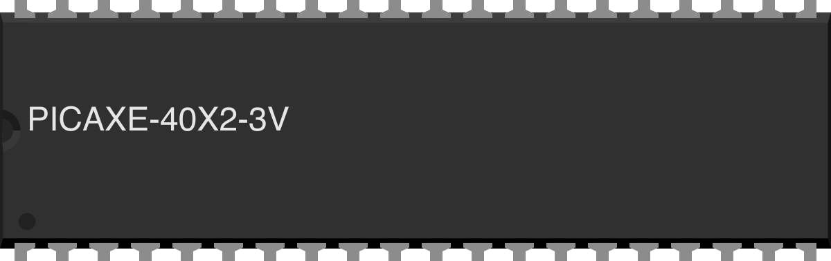
The PICAXE-40X2-3V is a versatile microcontroller manufactured by Revolution Education Ltd. It features 40 pins and is designed for easy programming and integration into a wide range of electronic projects. Operating at a voltage of 3V, this microcontroller is ideal for low-power applications and is compatible with various programming environments, including the PICAXE Programming Editor and Blockly.
Explore Projects Built with PICAXE-40X2-3V
 Open Project in Cirkit Designer
 Open Project in Cirkit Designer
 Open Project in Cirkit Designer
 Open Project in Cirkit Designer
Explore Projects Built with PICAXE-40X2-3V
Open Project in Cirkit DesignerOpen Project in Cirkit DesignerOpen Project in Cirkit DesignerOpen Project in Cirkit DesignerCommon Applications and Use Cases
- Robotics and automation systems
- Data acquisition and logging
- Home automation projects
- Educational tools for learning microcontroller programming
- Prototyping and hobbyist electronics
Technical Specifications
The following table outlines the key technical details of the PICAXE-40X2-3V microcontroller:
| Parameter | Value |
|---|---|
| Operating Voltage | 3V |
| Number of Pins | 40 |
| Clock Speed | Up to 64 MHz (internal resonator) |
| Programming Language | PICAXE BASIC, Blockly |
| Memory | 4096 bytes program memory |
| Input/Output Pins | 33 (configurable as digital or analog) |
| Communication Protocols | I2C, SPI, UART |
| ADC Resolution | 10-bit |
| Power Consumption | Low-power operation |
Pin Configuration and Descriptions
The PICAXE-40X2-3V has 40 pins, which are divided into power, input/output, and communication pins. Below is a summary of the pin configuration:
| Pin Number | Pin Name | Description |
|---|---|---|
| 1 | VSS | Ground (0V) |
| 11, 31 | VDD | Positive supply voltage (3V) |
| 2-9, 12-19 | I/O Pins | General-purpose input/output pins |
| 20, 21 | TX, RX | UART communication pins |
| 22, 23 | SDA, SCL | I2C communication pins |
| 24-27 | Analog Pins | Analog-to-digital converter (ADC) inputs |
| 28-30 | SPI Pins | Serial Peripheral Interface (SPI) communication |
| 32-40 | Additional I/O Pins | Configurable as digital or analog I/O pins |
Usage Instructions
How to Use the PICAXE-40X2-3V in a Circuit
- Power Supply: Connect the VDD pin to a 3V power source and the VSS pin to ground.
- Programming: Use the PICAXE Programming Editor or Blockly to write and upload code to the microcontroller. A USB-to-serial programming cable is required.
- I/O Configuration: Configure the pins as input or output in the code. For analog inputs, use the ADC pins.
- Communication: Utilize the UART, I2C, or SPI pins for interfacing with other devices such as sensors, displays, or other microcontrollers.
Important Considerations and Best Practices
- Ensure the supply voltage does not exceed 3V to avoid damaging the microcontroller.
- Use decoupling capacitors (e.g., 0.1 µF) near the power pins to stabilize the power supply.
- Avoid leaving unused input pins floating; connect them to ground or configure them as outputs.
- When using communication protocols, ensure proper pull-up resistors are used for I2C lines (SDA and SCL).
Example Code for Arduino UNO Integration
The PICAXE-40X2-3V can communicate with an Arduino UNO via UART. Below is an example code snippet for sending data from the Arduino to the PICAXE:
Arduino Code:
void setup() {
  Serial.begin(9600); // Initialize UART communication at 9600 baud
}

void loop() {
  Serial.println("Hello, PICAXE!"); // Send a message to the PICAXE
  delay(1000); // Wait for 1 second
}
PICAXE Code (BASIC):
main:
  serin [1000], C.7, ("Hello, PICAXE!") ' Receive data on pin C.7
  sertxd ("Message received", CR, LF)  ' Send acknowledgment via serial
  pause 1000                           ' Wait for 1 second
  goto main                            ' Repeat the process
Troubleshooting and FAQs
Common Issues and Solutions
Microcontroller Not Responding
- Cause: Incorrect power supply or loose connections.
- Solution: Verify that the VDD and VSS pins are properly connected to a 3V power source and ground.
Programming Errors
- Cause: Incorrect programming cable or software settings.
- Solution: Ensure the correct COM port is selected in the PICAXE Programming Editor and that the programming cable is securely connected.
Communication Problems
- Cause: Mismatched baud rates or incorrect wiring.
- Solution: Verify that the baud rate in the code matches the hardware settings and check the connections for UART, I2C, or SPI.
Analog Readings Are Inaccurate
- Cause: Noise or improper grounding.
- Solution: Use decoupling capacitors and ensure a stable ground connection.
FAQs
Q: Can the PICAXE-40X2-3V operate at 5V?
A: No, the PICAXE-40X2-3V is designed to operate at 3V. Using 5V may damage the microcontroller.Q: What programming languages are supported?
A: The PICAXE-40X2-3V supports PICAXE BASIC and Blockly for programming.Q: How many ADC channels are available?
A: The microcontroller has 4 ADC channels with a 10-bit resolution.Q: Can I use the PICAXE-40X2-3V with sensors and displays?
A: Yes, the microcontroller supports I2C, SPI, and UART communication, making it compatible with a wide range of sensors and displays.