
How to Use LSM303C (6 DOF): Examples, Pinouts, and Specs
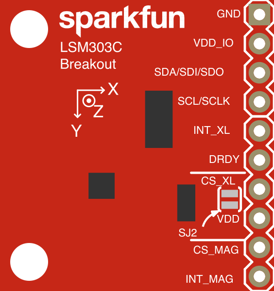
 Design with LSM303C (6 DOF) in Cirkit Designer
Introduction
The LSM303C is a 6-axis motion sensor that integrates a 3-axis accelerometer and a 3-axis magnetometer into a single compact package. This combination allows the sensor to detect orientation, motion, and magnetic field strength in three-dimensional space. It is widely used in applications such as robotics, drones, mobile devices, and other systems requiring precise motion tracking and navigation.
The LSM303C is particularly valued for its small size, low power consumption, and high sensitivity, making it ideal for portable and battery-powered devices.
Explore Projects Built with LSM303C (6 DOF)
 Open Project in Cirkit Designer
 Open Project in Cirkit Designer
 Open Project in Cirkit Designer
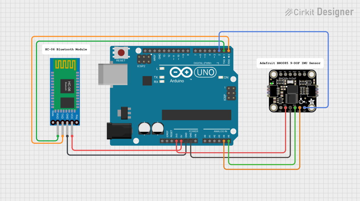 Open Project in Cirkit Designer
Explore Projects Built with LSM303C (6 DOF)
Open Project in Cirkit DesignerOpen Project in Cirkit DesignerOpen Project in Cirkit DesignerOpen Project in Cirkit DesignerTechnical Specifications
Key Technical Details
- Supply Voltage: 1.8V to 3.6V
- Accelerometer Full-Scale Range: ±2g, ±4g, ±8g
- Magnetometer Full-Scale Range: ±16 gauss
- Output Data Rate (ODR):
- Accelerometer: Up to 1.344 kHz
- Magnetometer: Up to 100 Hz
- Communication Interface: I²C or SPI
- Operating Temperature Range: -40°C to +85°C
- Package: LGA-12 (2 mm x 2 mm x 1 mm)
Pin Configuration and Descriptions
The LSM303C comes in a 12-pin LGA package. Below is the pin configuration:
| Pin Number | Pin Name | Description |
|---|---|---|
| 1 | VDD | Power supply (1.8V to 3.6V) |
| 2 | GND | Ground |
| 3 | SCL/SPC | I²C clock line / SPI clock |
| 4 | SDA/SDI/SDO | I²C data line / SPI data input/output |
| 5 | CS | SPI chip select (active low) |
| 6 | INT1 | Interrupt 1 output |
| 7 | INT2 | Interrupt 2 output |
| 8 | DRDY_M | Data-ready signal for magnetometer |
| 9 | DRDY_A | Data-ready signal for accelerometer |
| 10 | RES | Reserved (leave unconnected) |
| 11 | VDD_IO | I/O voltage reference |
| 12 | GND | Ground |
Usage Instructions
How to Use the LSM303C in a Circuit
- Power Supply: Connect the VDD pin to a 1.8V to 3.6V power source and the GND pins to ground.
- Communication Interface:
- For I²C: Connect the SCL and SDA pins to the corresponding I²C lines on your microcontroller. Pull-up resistors (typically 4.7kΩ) are required on both lines.
- For SPI: Connect the SPC, SDI/SDO, and CS pins to the corresponding SPI lines on your microcontroller.
- Interrupts: Use the INT1 and INT2 pins to handle interrupts for specific events, such as data-ready signals or threshold detection.
- Magnetometer and Accelerometer Data: Configure the sensor via the I²C or SPI interface to read data from the accelerometer and magnetometer registers.
Important Considerations and Best Practices
- Voltage Levels: Ensure that the I/O voltage (VDD_IO) matches the logic level of your microcontroller.
- Mounting: Place the sensor on a stable PCB to minimize vibrations and noise.
- Calibration: Perform calibration for both the accelerometer and magnetometer to improve accuracy.
- Magnetic Interference: Avoid placing the sensor near strong magnetic fields or ferromagnetic materials.
Example Code for Arduino UNO
Below is an example of how to interface the LSM303C with an Arduino UNO using the I²C protocol:
#include <Wire.h>

// LSM303C I2C address
#define LSM303C_ACC_ADDRESS  0x1D  // Accelerometer address
#define LSM303C_MAG_ADDRESS  0x1E  // Magnetometer address

// Register addresses
#define CTRL_REG1_A  0x20  // Accelerometer control register
#define CTRL_REG1_M  0x20  // Magnetometer control register
#define OUT_X_L_A    0x28  // Accelerometer X-axis low byte
#define OUT_X_L_M    0x28  // Magnetometer X-axis low byte

void setup() {
  Wire.begin();  // Initialize I2C communication
  Serial.begin(9600);  // Initialize serial communication

  // Configure accelerometer
  Wire.beginTransmission(LSM303C_ACC_ADDRESS);
  Wire.write(CTRL_REG1_A);
  Wire.write(0x57);  // Enable accelerometer, 100 Hz ODR
  Wire.endTransmission();

  // Configure magnetometer
  Wire.beginTransmission(LSM303C_MAG_ADDRESS);
  Wire.write(CTRL_REG1_M);
  Wire.write(0x60);  // Enable magnetometer, 10 Hz ODR
  Wire.endTransmission();
}

void loop() {
  int16_t accX, accY, accZ;

  // Read accelerometer data
  Wire.beginTransmission(LSM303C_ACC_ADDRESS);
  Wire.write(OUT_X_L_A | 0x80);  // Set auto-increment for multi-byte read
  Wire.endTransmission(false);
  Wire.requestFrom(LSM303C_ACC_ADDRESS, 6);

  if (Wire.available() == 6) {
    accX = Wire.read() | (Wire.read() << 8);
    accY = Wire.read() | (Wire.read() << 8);
    accZ = Wire.read() | (Wire.read() << 8);
  }

  // Print accelerometer data
  Serial.print("Acc X: "); Serial.print(accX);
  Serial.print(" | Acc Y: "); Serial.print(accY);
  Serial.print(" | Acc Z: "); Serial.println(accZ);

  delay(500);  // Wait for 500 ms
}
Troubleshooting and FAQs
Common Issues
- No Data Output:
- Ensure the sensor is powered correctly and the I²C/SPI connections are secure.
- Verify the I²C address or SPI configuration in your code.
- Incorrect Readings:
- Perform calibration to account for offsets and scaling errors.
- Check for magnetic interference or vibrations affecting the sensor.
- Communication Errors:
- Ensure pull-up resistors are present on the I²C lines.
- Verify that the microcontroller's logic level matches the sensor's VDD_IO.
Solutions and Tips
- Calibration: Use a known reference to calibrate the accelerometer and magnetometer.
- Debugging: Use a logic analyzer to monitor I²C or SPI communication for troubleshooting.
- Interrupts: Configure interrupts to reduce the need for constant polling of the sensor.
By following this documentation, you can effectively integrate the LSM303C into your projects for accurate motion and orientation sensing.