How to Use 8 Channel 5v Relay: Examples, Pinouts, and Specs
Introduction
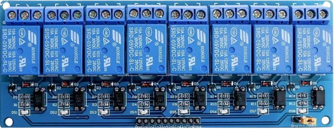
The 8 Channel 5V Relay (Manufacturer: AC, Part ID: Relay) is a versatile relay module designed to control multiple high-voltage devices using low-voltage signals, such as those from a microcontroller. This module features 8 independent relay channels, each capable of switching high-voltage loads, making it ideal for applications requiring control of multiple devices.
Explore Projects Built with 8 Channel 5v Relay


Explore Projects Built with 8 Channel 5v Relay
Common Applications and Use Cases
- Home automation systems (e.g., controlling lights, fans, or appliances)
- Industrial automation and control
- Robotics and mechatronics
- IoT (Internet of Things) projects
- Prototyping and educational projects
Technical Specifications
Below are the key technical details of the 8 Channel 5V Relay module:
| Parameter | Specification |
|---|---|
| Operating Voltage | 5V DC |
| Trigger Voltage | 3.3V to 5V (compatible with most MCUs) |
| Relay Type | Electromechanical |
| Number of Channels | 8 |
| Maximum Load Voltage | 250V AC / 30V DC |
| Maximum Load Current | 10A |
| Isolation | Optocoupler isolation for each channel |
| Dimensions | ~138mm x 56mm x 18mm |
| Weight | ~120g |
Pin Configuration and Descriptions
The module has two main interfaces: the control pins and the relay output terminals.
Control Pins
| Pin Name | Description |
|---|---|
| VCC | 5V power supply input for the module |
| GND | Ground connection |
| IN1 to IN8 | Control signals for each relay channel (active low) |
Relay Output Terminals
Each relay channel has three output terminals:
| Terminal | Description |
|---|---|
| COM | Common terminal |
| NO | Normally Open terminal (connected to COM when active) |
| NC | Normally Closed terminal (connected to COM when inactive) |
Usage Instructions
How to Use the Component in a Circuit
- Power the Module: Connect the VCC pin to a 5V DC power source and the GND pin to ground.
- Connect Control Signals: Use digital output pins from a microcontroller (e.g., Arduino UNO) to connect to the IN1 to IN8 pins. Each pin controls one relay channel.
- Connect the Load: For each relay channel, connect the load to the COM and NO/NC terminals:
- Use the NO terminal if the load should be off by default and turn on when the relay is activated.
- Use the NC terminal if the load should be on by default and turn off when the relay is activated.
- Activate the Relays: Send a LOW signal (0V) to the corresponding IN pin to activate the relay. A HIGH signal (5V) will deactivate it.
Important Considerations and Best Practices
- Power Supply: Ensure the module is powered with a stable 5V DC supply. Using a separate power supply for the relays and the microcontroller is recommended to avoid noise or voltage drops.
- Isolation: The module features optocoupler isolation to protect the microcontroller from high-voltage spikes. Ensure proper grounding for safety.
- Load Ratings: Do not exceed the maximum load voltage (250V AC / 30V DC) or current (10A) for each relay channel.
- Inductive Loads: When switching inductive loads (e.g., motors), use a flyback diode across the load to suppress voltage spikes.
Example: Connecting to an Arduino UNO
Below is an example of how to control the 8 Channel 5V Relay module using an Arduino UNO:
Circuit Connections
- Connect the module's VCC to the Arduino's 5V pin.
- Connect the module's GND to the Arduino's GND pin.
- Connect the module's IN1 to IN8 pins to Arduino digital pins 2 to 9, respectively.
- Connect a load (e.g., a light bulb) to the COM and NO terminals of one relay channel.
Arduino Code
// Example code to control an 8 Channel 5V Relay module with Arduino UNO

// Define the relay control pins
const int relayPins[] = {2, 3, 4, 5, 6, 7, 8, 9};

void setup() {
  // Initialize all relay pins as OUTPUT
  for (int i = 0; i < 8; i++) {
    pinMode(relayPins[i], OUTPUT);
    digitalWrite(relayPins[i], HIGH); // Set all relays to OFF state
  }
}

void loop() {
  // Example: Sequentially turn on each relay for 1 second
  for (int i = 0; i < 8; i++) {
    digitalWrite(relayPins[i], LOW);  // Turn ON relay (active LOW)
    delay(1000);                      // Wait for 1 second
    digitalWrite(relayPins[i], HIGH); // Turn OFF relay
  }
}
Troubleshooting and FAQs
Common Issues and Solutions
Relays Not Activating
- Cause: Insufficient power supply.
- Solution: Ensure the module is powered with a stable 5V DC source.
Microcontroller Resets When Relays Activate
- Cause: Voltage drop due to high current draw.
- Solution: Use a separate power supply for the relay module and the microcontroller.
Load Not Switching Properly
- Cause: Incorrect wiring of the load to the relay terminals.
- Solution: Verify the load is connected to the correct COM and NO/NC terminals.
Relays Stuck in ON/OFF State
- Cause: Faulty relay or excessive load current.
- Solution: Check the load current and replace the relay if necessary.
FAQs
Q: Can this module be used with a 3.3V microcontroller (e.g., ESP32)?
A: Yes, the module is compatible with 3.3V control signals, but ensure the VCC pin is still powered with 5V.
Q: Is it safe to control AC appliances with this module?
A: Yes, but ensure proper insulation and follow safety guidelines when working with high-voltage AC loads.
Q: Can I control all 8 relays simultaneously?
A: Yes, as long as the total current draw does not exceed the power supply's capacity.
Q: Do I need external components to use this module?
A: No additional components are required for basic operation, but a flyback diode is recommended for inductive loads.