
How to Use BD10KA5WF-E2: Examples, Pinouts, and Specs
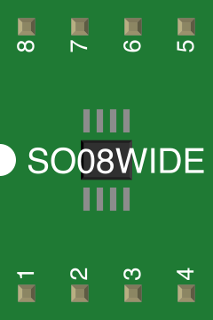
 Design with BD10KA5WF-E2 in Cirkit Designer
Introduction
The BD10KA5WF-E2, manufactured by ROHM Semiconductor, is a high-performance bridge rectifier designed for converting alternating current (AC) to direct current (DC). This component is known for its compact design, high efficiency, and robust performance, making it ideal for a wide range of applications. It is commonly used in power supplies, battery chargers, and other electronic circuits requiring AC-to-DC conversion.
Explore Projects Built with BD10KA5WF-E2
 Open Project in Cirkit Designer
 Open Project in Cirkit Designer
 Open Project in Cirkit Designer
 Open Project in Cirkit Designer
Explore Projects Built with BD10KA5WF-E2
Open Project in Cirkit DesignerOpen Project in Cirkit DesignerOpen Project in Cirkit DesignerOpen Project in Cirkit DesignerCommon Applications and Use Cases
- Power supply units for consumer electronics
- Battery charging circuits
- Industrial control systems
- LED drivers
- Renewable energy systems (e.g., solar inverters)
Technical Specifications
The following table outlines the key technical specifications of the BD10KA5WF-E2:
| Parameter | Value |
|---|---|
| Manufacturer | ROHM Semiconductor |
| Part Number | BD10KA5WF-E2 |
| Maximum Reverse Voltage | 1000 V |
| Forward Current (IF) | 10 A |
| Peak Surge Current (IFSM) | 200 A |
| Forward Voltage Drop (VF) | 1.1 V (typical) |
| Operating Temperature Range | -40°C to +150°C |
| Package Type | TO-220FP |
Pin Configuration and Descriptions
The BD10KA5WF-E2 is housed in a TO-220FP package with four pins. The pin configuration is as follows:
| Pin Number | Pin Name | Description |
|---|---|---|
| 1 | AC1 | AC input terminal 1 |
| 2 | AC2 | AC input terminal 2 |
| 3 | DC+ | Positive DC output terminal |
| 4 | DC- | Negative DC output terminal (Ground) |
Usage Instructions
How to Use the BD10KA5WF-E2 in a Circuit
Connect the AC Input Terminals:
- Connect the AC1 and AC2 pins to the AC voltage source. Ensure the input voltage does not exceed the maximum reverse voltage rating of 1000 V.
Connect the DC Output Terminals:
- Connect the DC+ pin to the positive side of the load and the DC- pin to the negative side (ground).
Add Filtering Components:
- To smooth the rectified DC output, connect a capacitor (e.g., electrolytic capacitor) across the DC+ and DC- terminals. The capacitor value depends on the desired ripple voltage and load current.
Heat Dissipation:
- The TO-220FP package includes a built-in heat sink. However, for high-current applications, consider adding an external heat sink to ensure proper thermal management.
Important Considerations and Best Practices
- Voltage Ratings: Ensure the input AC voltage does not exceed the maximum reverse voltage of 1000 V.
- Current Ratings: Do not exceed the maximum forward current of 10 A to avoid damaging the component.
- Thermal Management: Monitor the operating temperature and use a heat sink if necessary to maintain the temperature within the specified range (-40°C to +150°C).
- Polarity: Double-check the polarity of the DC output connections to prevent damage to the load or circuit.
Example Circuit with Arduino UNO
The BD10KA5WF-E2 can be used to power an Arduino UNO by rectifying an AC voltage source. Below is an example circuit and Arduino code to blink an LED:
Circuit Description:
- Use the BD10KA5WF-E2 to rectify a 12V AC source.
- Add a 1000 µF capacitor across the DC+ and DC- terminals for smoothing.
- Connect the DC+ and DC- terminals to the Arduino's VIN and GND pins, respectively.
- Connect an LED to pin 13 of the Arduino with a 220-ohm resistor.
Arduino Code:
// Simple LED Blink Program
// This code blinks an LED connected to pin 13 of the Arduino UNO.

void setup() {
  pinMode(13, OUTPUT); // Set pin 13 as an output pin
}

void loop() {
  digitalWrite(13, HIGH); // Turn the LED on
  delay(1000);            // Wait for 1 second
  digitalWrite(13, LOW);  // Turn the LED off
  delay(1000);            // Wait for 1 second
}
Troubleshooting and FAQs
Common Issues and Solutions
No Output Voltage:
- Cause: Incorrect wiring of the AC input or DC output terminals.
- Solution: Verify the connections to the AC1, AC2, DC+, and DC- pins.
Excessive Heat Generation:
- Cause: High current draw or insufficient heat dissipation.
- Solution: Add an external heat sink and ensure proper ventilation.
Ripple in DC Output:
- Cause: Insufficient filtering.
- Solution: Increase the capacitance of the smoothing capacitor.
Component Damage:
- Cause: Exceeding voltage or current ratings.
- Solution: Ensure the input voltage and load current are within the specified limits.
FAQs
Q1: Can the BD10KA5WF-E2 handle 3-phase AC input?
A1: No, the BD10KA5WF-E2 is designed for single-phase AC input only.
Q2: What is the recommended capacitor value for smoothing?
A2: The capacitor value depends on the load current and desired ripple voltage. A typical value is 1000 µF for moderate loads.
Q3: Can this component be used in high-frequency applications?
A3: The BD10KA5WF-E2 is optimized for standard AC mains frequencies (50/60 Hz). For high-frequency rectification, consider using fast recovery diodes or Schottky diodes.
Q4: Is the TO-220FP package electrically isolated?
A4: Yes, the TO-220FP package provides electrical isolation between the heat sink and the internal circuitry, simplifying thermal management.