How to Use oled display: Examples, Pinouts, and Specs
Introduction
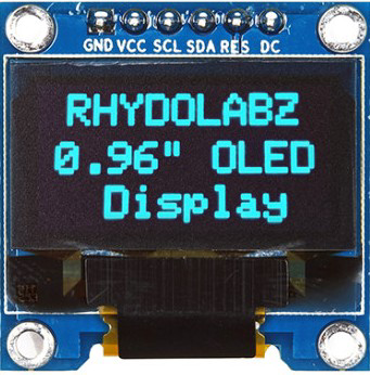
An OLED (Organic Light Emitting Diode) display is a screen technology that uses organic compounds to emit light when an electric current is applied. Unlike traditional LCDs, OLED displays do not require a backlight, resulting in deeper blacks, higher contrast ratios, and improved energy efficiency. These displays are known for their vibrant colors, wide viewing angles, and fast response times.
Common applications of OLED displays include:
- Consumer electronics such as smartphones, tablets, and televisions
- Wearable devices like smartwatches and fitness trackers
- Embedded systems and microcontroller projects
- Industrial equipment and medical devices for compact, high-contrast displays
Explore Projects Built with oled display
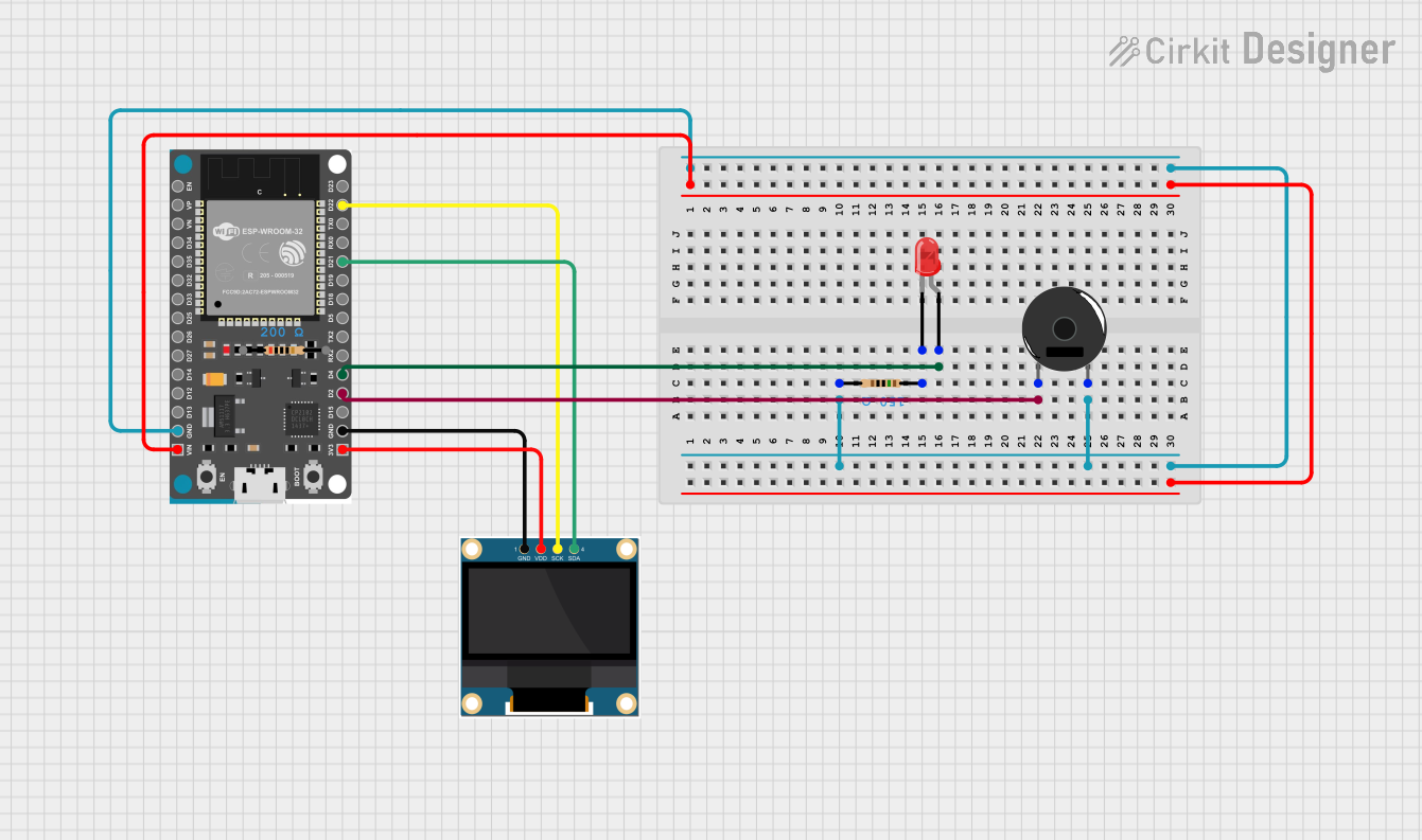


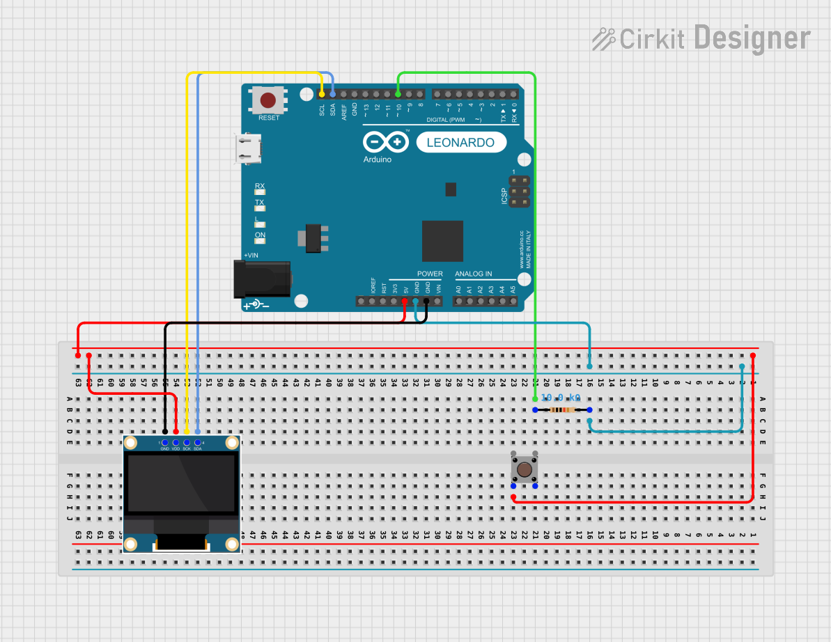
Explore Projects Built with oled display
Technical Specifications
Below are the general technical specifications for a typical small OLED display module (e.g., 128x64 resolution):
| Parameter | Value |
|---|---|
| Display Type | OLED (Organic Light Emitting Diode) |
| Resolution | 128x64 pixels |
| Interface | I2C or SPI |
| Operating Voltage | 3.3V to 5V |
| Current Consumption | ~20mA (varies with brightness) |
| Viewing Angle | >160° |
| Pixel Color | Monochrome (white, blue, or yellow) |
| Dimensions | ~27mm x 27mm x 4mm (varies by model) |
| Operating Temperature | -40°C to +85°C |
Pin Configuration (I2C Interface)
The following table describes the pinout for a typical 4-pin I2C OLED display module:
| Pin | Name | Description |
|---|---|---|
| 1 | GND | Ground (0V reference) |
| 2 | VCC | Power supply (3.3V or 5V) |
| 3 | SCL | Serial Clock Line (I2C clock input) |
| 4 | SDA | Serial Data Line (I2C data input/output) |
Pin Configuration (SPI Interface)
For SPI-based OLED modules, the pinout may look like this:
| Pin | Name | Description |
|---|---|---|
| 1 | GND | Ground (0V reference) |
| 2 | VCC | Power supply (3.3V or 5V) |
| 3 | SCK | Serial Clock (SPI clock input) |
| 4 | MOSI | Master Out Slave In (SPI data input) |
| 5 | RES | Reset (active low) |
| 6 | DC | Data/Command control |
| 7 | CS | Chip Select (active low) |
Usage Instructions
Connecting the OLED Display to an Arduino UNO (I2C)
Wiring: Connect the OLED display to the Arduino UNO as follows:
- GND → GND
- VCC → 5V
- SCL → A5 (I2C clock line on Arduino UNO)
- SDA → A4 (I2C data line on Arduino UNO)
Install Required Libraries:
- Install the
Adafruit_GFXandAdafruit_SSD1306libraries in the Arduino IDE. These libraries provide functions to control the OLED display.
- Install the
Upload Example Code: Use the following example code to display text on the OLED:
// Include necessary libraries
#include <Adafruit_GFX.h>       // Graphics library for OLED
#include <Adafruit_SSD1306.h>  // Driver for SSD1306 OLED

// Define OLED display dimensions
#define SCREEN_WIDTH 128
#define SCREEN_HEIGHT 64

// Create an instance of the display object
Adafruit_SSD1306 display(SCREEN_WIDTH, SCREEN_HEIGHT, &Wire, -1);

void setup() {
  // Initialize the display
  if (!display.begin(SSD1306_I2C_ADDRESS, 0x3C)) {
    // Check if the display is connected
    Serial.println(F("SSD1306 allocation failed"));
    for (;;); // Halt execution if initialization fails
  }

  // Clear the display buffer
  display.clearDisplay();

  // Set text size and color
  display.setTextSize(1);      // Small text size
  display.setTextColor(SSD1306_WHITE); // White text

  // Display a message
  display.setCursor(0, 0);     // Set cursor to top-left corner
  display.println(F("Hello, OLED!"));
  display.display();           // Render the text on the screen
}

void loop() {
  // Nothing to do here
}
Important Considerations
- Power Supply: Ensure the OLED module is powered within its specified voltage range (3.3V or 5V). Exceeding this range may damage the display.
- I2C Address: Most OLED modules use the default I2C address
0x3C. If the display does not respond, check the address or use an I2C scanner sketch to detect it. - Contrast and Brightness: Adjust the brightness settings in the library if the display appears too dim or too bright.
- Reset Pin: If your module has a reset pin, connect it to a GPIO pin on the microcontroller or tie it to the ground if not used.
Troubleshooting and FAQs
Common Issues
The display does not turn on:
- Verify the wiring connections, especially the power (VCC and GND) and I2C lines (SCL and SDA).
- Check if the OLED module is receiving the correct voltage.
Nothing appears on the screen:
- Ensure the correct I2C address (
0x3Cor0x3D) is used in the code. - Confirm that the required libraries (
Adafruit_GFXandAdafruit_SSD1306) are installed and up to date.
- Ensure the correct I2C address (
Flickering or unstable display:
- Use shorter wires to reduce noise in the I2C or SPI lines.
- Add pull-up resistors (4.7kΩ to 10kΩ) to the SDA and SCL lines if not already present.
Partial or distorted display output:
- Check for loose connections or damaged pins.
- Ensure the display dimensions (e.g., 128x64) are correctly defined in the code.
FAQs
Q: Can I use the OLED display with a 3.3V microcontroller?
A: Yes, most OLED modules are compatible with both 3.3V and 5V systems. Check the module's datasheet to confirm.
Q: How do I display custom graphics or images?
A: Use tools like LCD Assistant or online converters to generate bitmap arrays for your graphics. Then, use the drawBitmap() function in the Adafruit_GFX library to render the image.
Q: Can I use multiple OLED displays on the same I2C bus?
A: Yes, but each display must have a unique I2C address. Some modules allow address changes via solder jumpers.
Q: What is the lifespan of an OLED display?
A: OLED displays typically have a lifespan of 10,000 to 50,000 hours, depending on usage and brightness settings.