How to Use resisitve touch screen: Examples, Pinouts, and Specs
Introduction
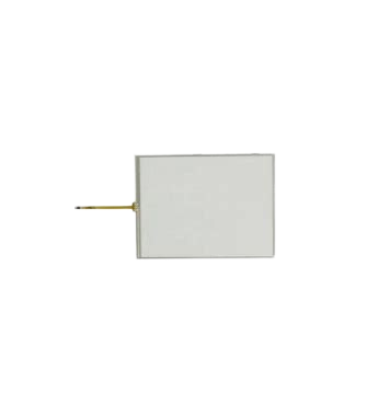
A resistive touch screen is a type of touch-sensitive device that detects touch input through the pressure applied to its surface. It consists of two flexible layers separated by a small gap, and when pressure is applied, the layers make contact, registering the touch location. This technology is widely used due to its simplicity, durability, and cost-effectiveness.
Explore Projects Built with resisitve touch screen
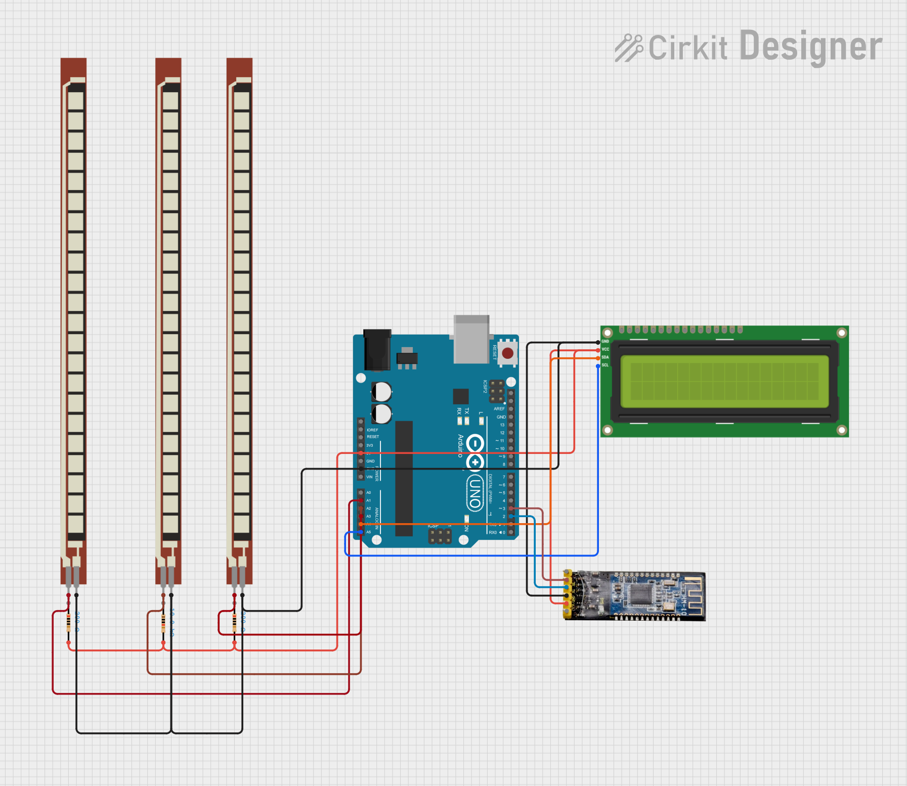
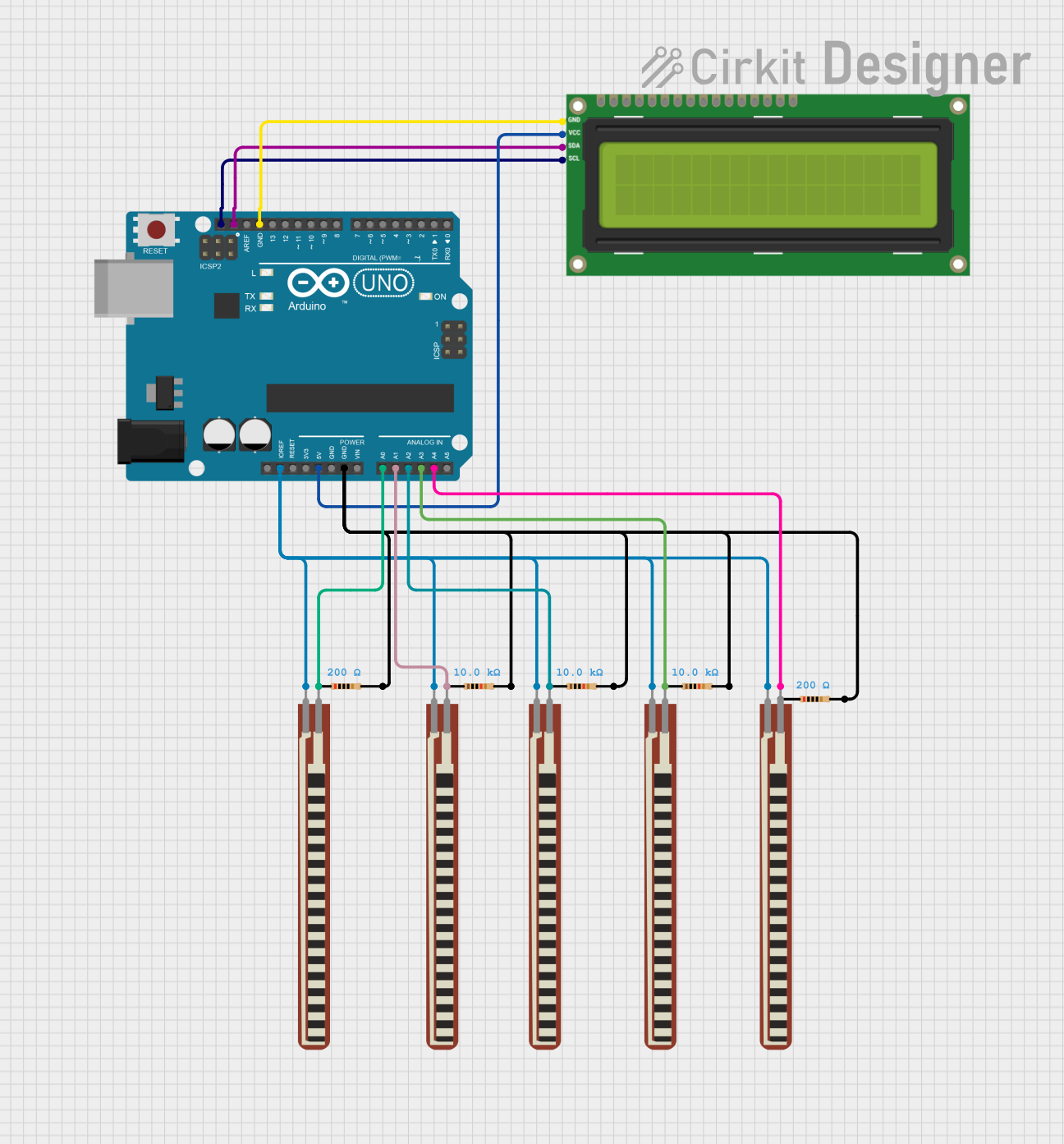
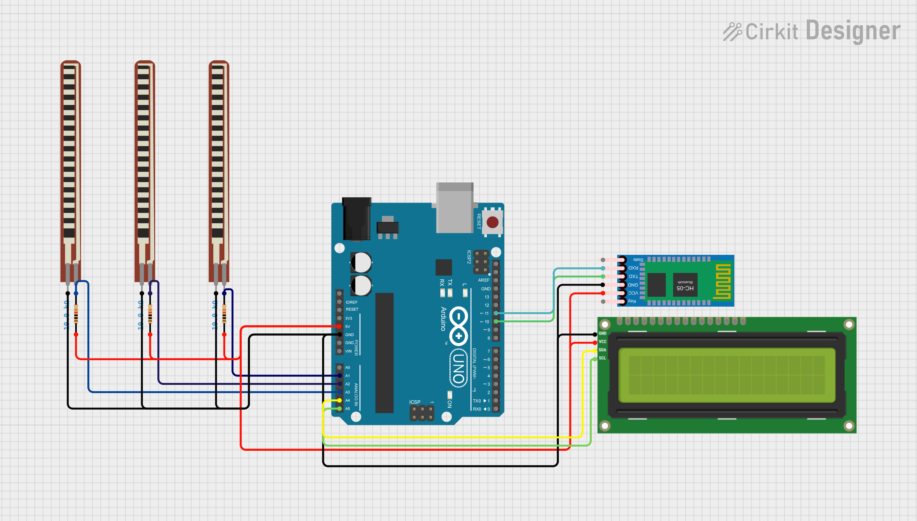
Explore Projects Built with resisitve touch screen
Common Applications and Use Cases
- Point-of-sale (POS) systems
- Industrial control panels
- Handheld devices such as PDAs
- Automotive navigation systems
- Medical equipment interfaces
- Consumer electronics like ATMs and kiosks
Technical Specifications
Below are the key technical details for a 4-wire resistive touch screen:
| Parameter | Value |
|---|---|
| Operating Voltage | 3.3V to 5V |
| Operating Current | < 1mA |
| Contact Resistance | 100Ω to 1kΩ |
| Insulation Resistance | > 20MΩ at 25V DC |
| Touch Activation Force | 20g to 80g |
| Response Time | < 10ms |
| Operating Temperature | -10°C to 60°C |
| Storage Temperature | -20°C to 70°C |
| Lifespan | > 1 million touches |
Pin Configuration and Descriptions
The 4-wire resistive touch screen has four pins, typically labeled as follows:
| Pin Name | Description |
|---|---|
| X+ | Positive terminal for the X-axis. Used to measure horizontal touch coordinates. |
| X- | Negative terminal for the X-axis. Completes the X-axis circuit. |
| Y+ | Positive terminal for the Y-axis. Used to measure vertical touch coordinates. |
| Y- | Negative terminal for the Y-axis. Completes the Y-axis circuit. |
Usage Instructions
How to Use the Component in a Circuit
Connect the Pins:
- Connect the X+ and X- pins to an analog input or GPIO pins of your microcontroller.
- Similarly, connect the Y+ and Y- pins to another set of analog input or GPIO pins.
- Ensure proper pull-up or pull-down resistors if required by your microcontroller.
Power Supply:
- Provide a stable voltage supply (3.3V or 5V) as per the specifications of your microcontroller.
Reading Touch Coordinates:
- To detect a touch, apply voltage across one axis (e.g., X+ and X-) and read the voltage on the other axis (e.g., Y+ and Y-).
- Switch the voltage application to the other axis and repeat the process to get both X and Y coordinates.
Debouncing:
- Implement software debouncing to filter out noise and ensure accurate touch detection.
Important Considerations and Best Practices
- Avoid Excessive Force: Do not apply excessive pressure to the screen, as it may damage the layers.
- Calibration: Calibrate the touch screen to ensure accurate coordinate mapping.
- Environmental Protection: Use protective covers or enclosures in harsh environments to prevent damage from dust, moisture, or chemicals.
- Signal Conditioning: Use capacitors or filters to reduce noise in the analog signals.
Example Code for Arduino UNO
Below is an example of how to interface a 4-wire resistive touch screen with an Arduino UNO:
// Example code to read X and Y coordinates from a 4-wire resistive touch screen
// Connect X+ to A0, X- to A1, Y+ to A2, and Y- to A3 on the Arduino UNO

#define X_PLUS A0  // X+ pin connected to analog pin A0
#define X_MINUS A1 // X- pin connected to analog pin A1
#define Y_PLUS A2  // Y+ pin connected to analog pin A2
#define Y_MINUS A3 // Y- pin connected to analog pin A3

void setup() {
  Serial.begin(9600); // Initialize serial communication for debugging

  // Set pin modes
  pinMode(X_PLUS, INPUT);
  pinMode(X_MINUS, INPUT);
  pinMode(Y_PLUS, INPUT);
  pinMode(Y_MINUS, INPUT);
}

void loop() {
  int x, y;

  // Read X coordinate
  pinMode(X_PLUS, OUTPUT);
  pinMode(X_MINUS, OUTPUT);
  digitalWrite(X_PLUS, HIGH);
  digitalWrite(X_MINUS, LOW);
  pinMode(Y_PLUS, INPUT);
  pinMode(Y_MINUS, INPUT);
  x = analogRead(Y_PLUS); // Read voltage on Y+ to get X coordinate

  // Read Y coordinate
  pinMode(Y_PLUS, OUTPUT);
  pinMode(Y_MINUS, OUTPUT);
  digitalWrite(Y_PLUS, HIGH);
  digitalWrite(Y_MINUS, LOW);
  pinMode(X_PLUS, INPUT);
  pinMode(X_MINUS, INPUT);
  y = analogRead(X_PLUS); // Read voltage on X+ to get Y coordinate

  // Print coordinates to the serial monitor
  Serial.print("X: ");
  Serial.print(x);
  Serial.print(" Y: ");
  Serial.println(y);

  delay(100); // Small delay for stability
}
Troubleshooting and FAQs
Common Issues and Solutions
No Response from the Touch Screen:
- Cause: Loose or incorrect wiring.
- Solution: Double-check all connections and ensure proper pin mapping.
Inaccurate Touch Coordinates:
- Cause: Lack of calibration or noisy signals.
- Solution: Perform a calibration routine and add signal filtering.
Touch Screen Not Detecting Touch:
- Cause: Insufficient touch pressure or damaged layers.
- Solution: Apply slightly more pressure or inspect the screen for physical damage.
Fluctuating Readings:
- Cause: Electrical noise or poor grounding.
- Solution: Use capacitors for noise filtering and ensure a proper ground connection.
FAQs
Q: Can this touch screen detect multiple touches simultaneously?
A: No, resistive touch screens are designed for single-touch input only.
Q: How do I calibrate the touch screen?
A: Calibration involves mapping the raw analog readings to screen coordinates. This can be done using a software routine that asks the user to touch specific points on the screen.
Q: Is the resistive touch screen waterproof?
A: Standard resistive touch screens are not waterproof. Use a protective enclosure for outdoor or wet environments.
Q: Can I use this with a Raspberry Pi?
A: Yes, the resistive touch screen can be interfaced with a Raspberry Pi using its GPIO pins and ADC (analog-to-digital converter) modules.
This concludes the documentation for the 4-wire resistive touch screen.