How to Use Mini Step Up 5V 8V 9V 12V: Examples, Pinouts, and Specs
Introduction
The Mini Step Up 5V 8V 9V 12V (Manufacturer Part ID: penaik volt) is a compact DC-DC boost converter designed to increase a lower input voltage to a higher, stable output voltage. Manufactured by Alibaba, this versatile module is ideal for applications requiring a reliable power source for devices operating at 5V, 8V, 9V, or 12V. Its small size and efficiency make it suitable for portable electronics, battery-powered devices, and DIY projects.
Explore Projects Built with Mini Step Up 5V 8V 9V 12V


Explore Projects Built with Mini Step Up 5V 8V 9V 12V
Common Applications
- Powering microcontrollers (e.g., Arduino, Raspberry Pi) from lower voltage sources.
- Boosting voltage from batteries (e.g., 3.7V Li-ion) to power 5V or 12V devices.
- Portable chargers and USB-powered devices.
- DIY electronics and robotics projects.
Technical Specifications
The following table outlines the key technical details of the Mini Step Up module:
| Parameter | Value |
|---|---|
| Input Voltage Range | 2V to 24V |
| Output Voltage Options | 5V, 8V, 9V, 12V (selectable via jumper) |
| Maximum Output Current | 2A (varies with input voltage and load) |
| Efficiency | Up to 93% (depending on input/output ratio) |
| Dimensions | 22mm x 17mm x 4mm |
| Weight | 3 grams |
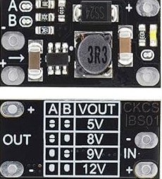
Pin Configuration and Descriptions
The module has a simple pin layout for easy integration into circuits:
| Pin Name | Description |
|---|---|
| VIN | Positive input voltage (2V to 24V) |
| GND | Ground (common for input and output) |
| VOUT | Positive output voltage (5V, 8V, 9V, or 12V) |
Usage Instructions
How to Use the Component in a Circuit
Connect Input Voltage:
- Attach the positive terminal of your power source to the
VINpin. - Connect the negative terminal of your power source to the
GNDpin. - Ensure the input voltage is within the 2V to 24V range.
- Attach the positive terminal of your power source to the
Select Output Voltage:
- Use the onboard jumper or solder pads to select the desired output voltage (5V, 8V, 9V, or 12V).
- Refer to the module's markings or datasheet for jumper configuration.
Connect Load:
- Attach the positive terminal of your load to the
VOUTpin. - Connect the negative terminal of your load to the
GNDpin.
- Attach the positive terminal of your load to the
Power On:
- Turn on the input power source. The module will boost the input voltage to the selected output voltage.
Important Considerations and Best Practices
- Input Voltage: Ensure the input voltage is within the specified range. Exceeding the maximum input voltage may damage the module.
- Output Current: The maximum output current depends on the input voltage and load. Avoid exceeding 2A to prevent overheating.
- Heat Dissipation: For high-power applications, consider adding a heatsink or ensuring proper ventilation to prevent thermal shutdown.
- Polarity: Double-check connections to avoid reverse polarity, which can damage the module.
Example: Using with Arduino UNO
To power an Arduino UNO from a 3.7V Li-ion battery using the Mini Step Up module:
- Set the output voltage to 5V using the jumper.
- Connect the battery's positive terminal to
VINand negative terminal toGND. - Connect the
VOUTpin to the Arduino's 5V pin andGNDto the Arduino's GND pin.
Here is an example Arduino sketch to blink an LED while powered by the Mini Step Up module:
// Blink an LED connected to pin 13 of the Arduino UNO
// Ensure the Mini Step Up module is set to output 5V

void setup() {
  pinMode(13, OUTPUT); // Set pin 13 as an output
}

void loop() {
  digitalWrite(13, HIGH); // Turn the LED on
  delay(1000);            // Wait for 1 second
  digitalWrite(13, LOW);  // Turn the LED off
  delay(1000);            // Wait for 1 second
}
Troubleshooting and FAQs
Common Issues and Solutions
No Output Voltage:
- Verify the input voltage is within the 2V to 24V range.
- Check the jumper configuration for the correct output voltage setting.
- Ensure all connections are secure and polarity is correct.
Overheating:
- Reduce the load current if the module becomes too hot.
- Improve ventilation or add a heatsink for better heat dissipation.
Output Voltage Fluctuations:
- Ensure the input voltage is stable and sufficient for the desired output.
- Check for loose connections or damaged components.
Module Not Working After Connection:
- Inspect for reverse polarity damage. Replace the module if necessary.
FAQs
Q: Can I use this module to power a 12V motor?
A: Yes, but ensure the input voltage and current can support the motor's power requirements. The module's maximum output current is 2A.
Q: How do I know the efficiency of the module?
A: Efficiency depends on the input and output voltage ratio. For optimal efficiency, keep the input voltage as close as possible to the desired output voltage.
Q: Can I use this module with a solar panel?
A: Yes, as long as the solar panel's output voltage is within the 2V to 24V range and provides sufficient current for your load.
Q: Is the output voltage adjustable?
A: No, the output voltage is fixed to 5V, 8V, 9V, or 12V, depending on the jumper configuration.