How to Use 2x 3.7V Battery Pack: Examples, Pinouts, and Specs
Introduction
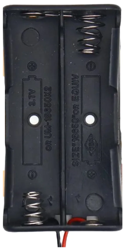
The 2x 3.7V Battery Pack is a versatile power source consisting of two 3.7V lithium-ion cells. These cells can be connected in either series or parallel configurations, depending on the desired output. When connected in series, the pack provides a higher voltage of 7.4V, suitable for devices requiring more power. In parallel configuration, the pack delivers the same 3.7V output but with increased capacity, extending the runtime of your devices.
This battery pack is commonly used in portable electronics, robotics, RC vehicles, IoT devices, and DIY projects. Its compact size and rechargeable nature make it an ideal choice for applications requiring reliable and efficient power.
Explore Projects Built with 2x 3.7V Battery Pack


Explore Projects Built with 2x 3.7V Battery Pack
Technical Specifications
General Specifications
- Battery Type: Lithium-ion
- Nominal Voltage:
- Series Configuration: 7.4V
- Parallel Configuration: 3.7V
- Capacity: Varies based on individual cell capacity (e.g., 2000mAh per cell results in 4000mAh in parallel)
- Maximum Discharge Current: Depends on the cell specifications (e.g., 10A for high-drain cells)
- Charging Voltage:
- Series Configuration: 8.4V
- Parallel Configuration: 4.2V
- Charging Current: Typically 0.5C to 1C of the cell capacity (e.g., 1A for a 2000mAh cell)
- Protection Circuit: Optional (overcharge, over-discharge, and short-circuit protection)
Pin Configuration and Descriptions
The battery pack typically has two terminals for connection:
| Pin Name | Description |
|---|---|
| Positive (+) | Positive terminal of the battery pack |
| Negative (-) | Negative terminal of the battery pack |
Some battery packs may include additional wires for balance charging or monitoring. These are typically labeled as follows:
| Pin Name | Description |
|---|---|
| B+ | Positive terminal of the first cell |
| B- | Negative terminal of the second cell |
| BM | Middle connection between the two cells (optional) |
Usage Instructions
Connecting the Battery Pack
- Determine the Configuration:
- For higher voltage (7.4V), connect the cells in series.
- For higher capacity (3.7V), connect the cells in parallel.
- Connect to the Circuit:
- Ensure the positive terminal of the battery pack is connected to the positive input of your circuit.
- Connect the negative terminal to the ground or negative input of your circuit.
- Use a Protection Circuit:
- If the battery pack does not include a built-in protection circuit, consider adding one to prevent overcharging, over-discharging, and short circuits.
Charging the Battery Pack
- Use a lithium-ion battery charger compatible with the pack's configuration:
- For series configuration, use a charger with an 8.4V output.
- For parallel configuration, use a charger with a 4.2V output.
- Avoid overcharging or leaving the battery connected to the charger for extended periods.
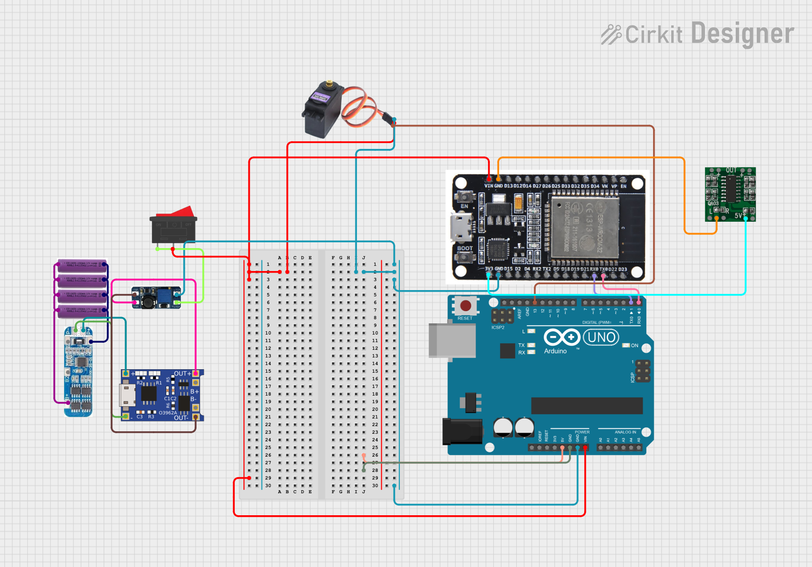
Example: Using with Arduino UNO
To power an Arduino UNO with the 2x 3.7V Battery Pack:
- Connect the positive terminal of the battery pack to the VIN pin of the Arduino.
- Connect the negative terminal to the GND pin.
- Ensure the battery pack is in series configuration (7.4V) to provide sufficient voltage for the Arduino's onboard voltage regulator.
Sample Code for Monitoring Battery Voltage
You can use a voltage divider circuit to monitor the battery voltage with the Arduino UNO. Here's an example:
// Define the analog pin connected to the voltage divider
const int voltagePin = A0;

// Voltage divider resistor values (in ohms)
const float R1 = 10000.0; // Resistor connected to battery positive
const float R2 = 10000.0; // Resistor connected to ground

void setup() {
  Serial.begin(9600); // Initialize serial communication
}

void loop() {
  int sensorValue = analogRead(voltagePin); // Read the analog value
  float voltage = sensorValue * (5.0 / 1023.0); // Convert to voltage
  voltage = voltage * ((R1 + R2) / R2); // Adjust for voltage divider ratio

  Serial.print("Battery Voltage: ");
  Serial.print(voltage);
  Serial.println(" V");

  delay(1000); // Wait for 1 second before the next reading
}
Note: Ensure the voltage divider reduces the battery voltage to within the Arduino's ADC input range (0-5V).
Important Considerations
- Polarity: Always double-check the polarity before connecting the battery pack to your circuit.
- Heat Management: Avoid exposing the battery pack to high temperatures, as this can damage the cells.
- Storage: Store the battery pack at a partial charge (around 50%) in a cool, dry place when not in use for extended periods.
Troubleshooting and FAQs
Common Issues
Battery Pack Not Charging:
- Cause: Faulty charger or incorrect charging voltage.
- Solution: Verify the charger specifications and ensure compatibility with the battery pack configuration.
Short Runtime:
- Cause: Degraded battery cells or high current draw.
- Solution: Test the individual cells for capacity and replace if necessary. Reduce the load on the battery pack.
Overheating During Use:
- Cause: Excessive current draw or damaged cells.
- Solution: Ensure the load does not exceed the maximum discharge current. Replace damaged cells.
Voltage Drop Under Load:
- Cause: High internal resistance of the cells.
- Solution: Replace the cells with new ones or use cells with a higher discharge rating.
FAQs
Q1: Can I use this battery pack to power a 5V device?
A1: Yes, but you will need a voltage regulator or DC-DC converter to step down the voltage to 5V.
Q2: How do I know if the battery pack is fully charged?
A2: A fully charged lithium-ion cell has a voltage of 4.2V. For a series configuration, the pack voltage will be 8.4V.
Q3: Can I connect more than two cells in this pack?
A3: Yes, you can connect additional cells in series or parallel, but ensure the charger and protection circuit are compatible with the new configuration.
Q4: Is it safe to use the battery pack without a protection circuit?
A4: It is not recommended. A protection circuit ensures safe operation by preventing overcharging, over-discharging, and short circuits.