How to Use UHF RFID FM-505: Examples, Pinouts, and Specs
Introduction
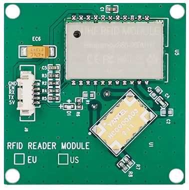
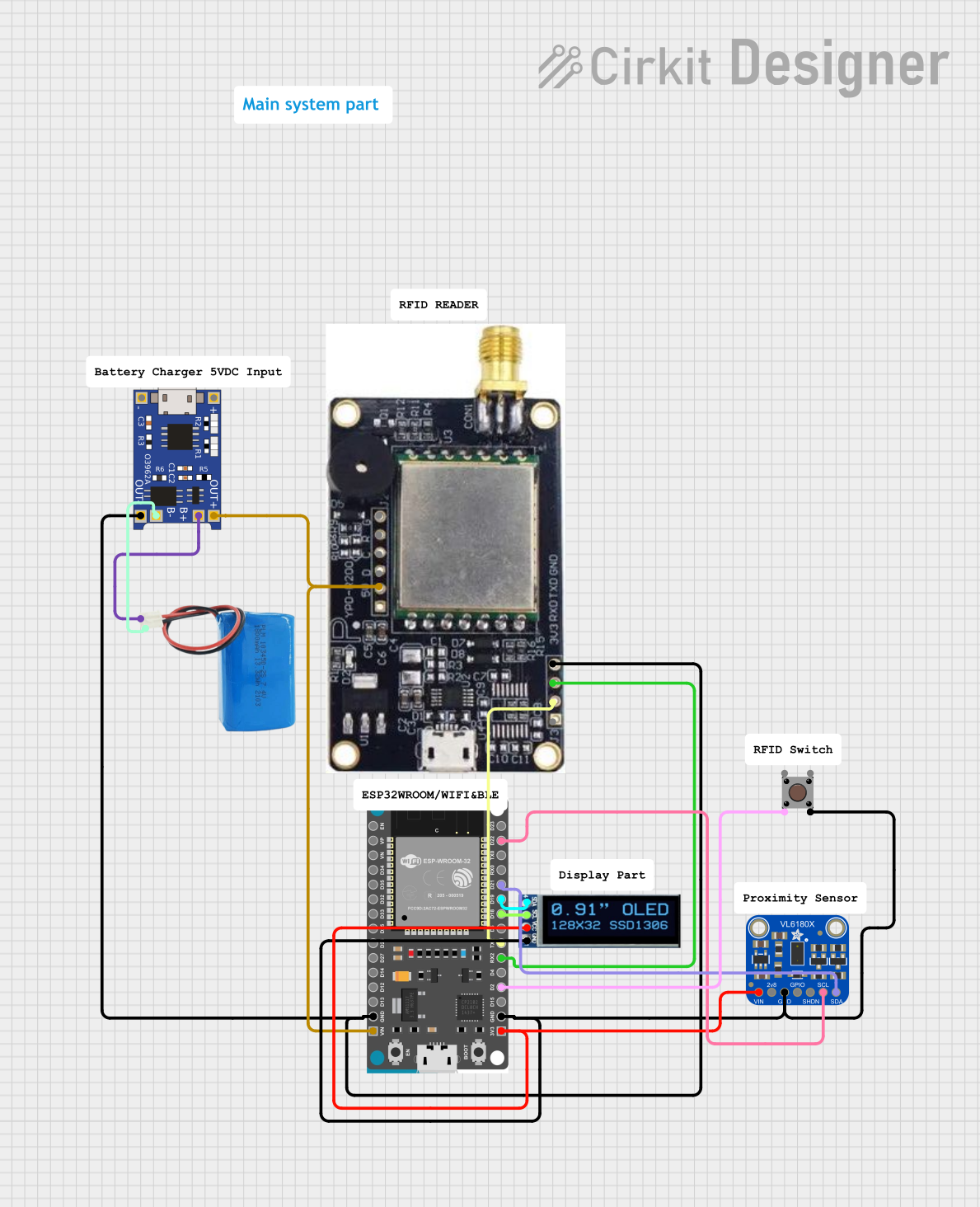
The UHF RFID FM-505, manufactured by Fonkan (Part ID: RFID), is a high-frequency RFID module designed for wireless identification and tracking. Operating in the UHF band, this module is widely used in various applications such as inventory management, asset tracking, access control, and supply chain logistics. Its robust performance and ease of integration make it a popular choice for both hobbyists and professionals.
Explore Projects Built with UHF RFID FM-505
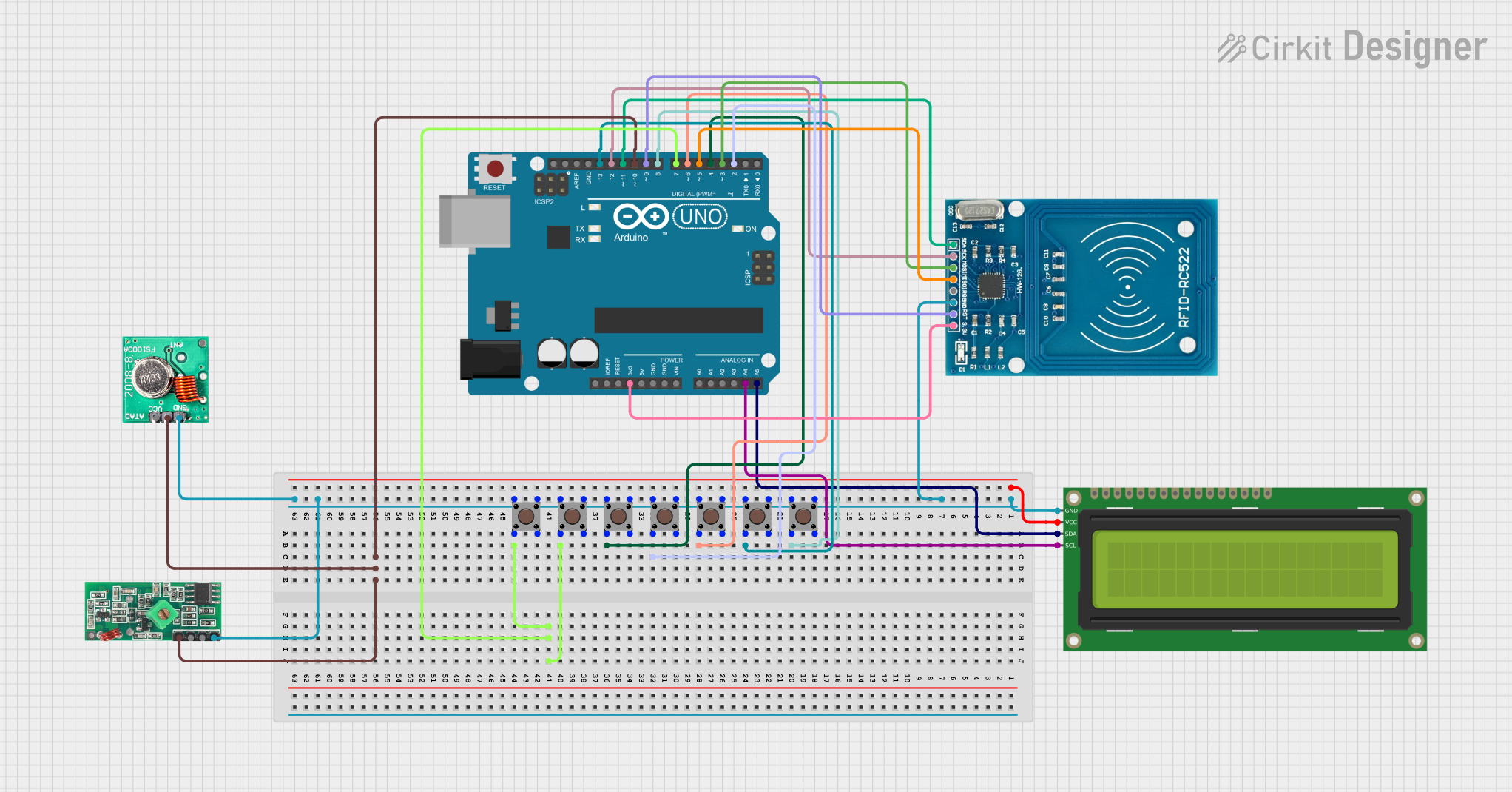
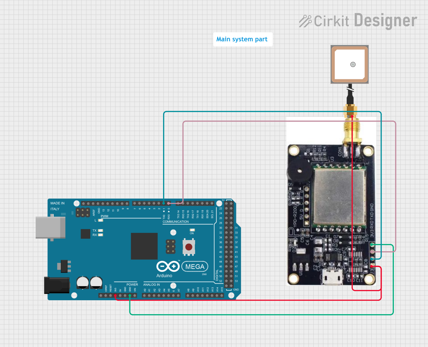
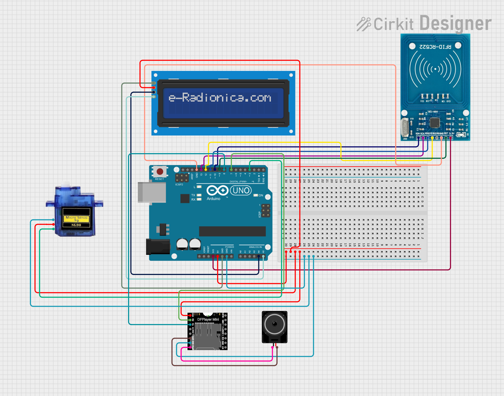
Explore Projects Built with UHF RFID FM-505
Technical Specifications
Key Technical Details
| Parameter | Value |
|---|---|
| Operating Frequency | 860-960 MHz |
| Output Power | 0-30 dBm (adjustable) |
| Communication Interface | UART, RS232, RS485 |
| Power Supply | 3.3V - 5V DC |
| Current Consumption | < 200mA |
| Reading Distance | Up to 10 meters (depending on tag and environment) |
| Antenna | External (SMA connector) |
| Dimensions | 60mm x 40mm x 5mm |
Pin Configuration and Descriptions
| Pin Number | Pin Name | Description |
|---|---|---|
| 1 | VCC | Power Supply (3.3V - 5V DC) |
| 2 | GND | Ground |
| 3 | TX | UART Transmit |
| 4 | RX | UART Receive |
| 5 | RS232_TX | RS232 Transmit |
| 6 | RS232_RX | RS232 Receive |
| 7 | RS485_A | RS485 Data Line A |
| 8 | RS485_B | RS485 Data Line B |
| 9 | ANT | Antenna Connector (SMA) |
Usage Instructions
How to Use the Component in a Circuit
- Power Supply: Connect the VCC pin to a 3.3V or 5V DC power source and the GND pin to the ground.
- Communication Interface: Choose the appropriate communication interface (UART, RS232, or RS485) based on your application. For example, if using UART, connect the TX pin of the FM-505 to the RX pin of your microcontroller and the RX pin of the FM-505 to the TX pin of your microcontroller.
- Antenna: Attach an external antenna to the ANT connector (SMA) to ensure optimal reading distance and performance.
- Initialization: Initialize the communication interface in your microcontroller code and configure the RFID module settings as needed.
Important Considerations and Best Practices
- Power Supply: Ensure a stable power supply to avoid fluctuations that could affect the module's performance.
- Antenna Placement: Position the antenna away from metal objects and other sources of interference to maximize reading distance.
- Baud Rate: Configure the baud rate of the communication interface to match the module's default settings (typically 9600 bps).
- Environment: Be aware that environmental factors such as obstacles and tag orientation can affect the reading distance and accuracy.
Example Code for Arduino UNO
#include <SoftwareSerial.h>

// Define the pins for SoftwareSerial
SoftwareSerial rfidSerial(10, 11); // RX, TX

void setup() {
  // Initialize hardware serial for debugging
  Serial.begin(9600);
  // Initialize software serial for RFID module
  rfidSerial.begin(9600);
  Serial.println("RFID Module Initialized");
}

void loop() {
  // Check if data is available from the RFID module
  if (rfidSerial.available()) {
    // Read the data from the RFID module
    String rfidData = rfidSerial.readString();
    // Print the RFID data to the serial monitor
    Serial.println("RFID Tag Detected: " + rfidData);
  }
}
Troubleshooting and FAQs
Common Issues Users Might Face
No Response from the Module:
- Solution: Check the power connections and ensure the module is receiving the correct voltage. Verify the communication interface connections and settings.
Short Reading Distance:
- Solution: Ensure the antenna is properly connected and positioned. Check for any sources of interference and adjust the antenna placement.
Data Corruption:
- Solution: Verify the baud rate settings and ensure they match between the RFID module and the microcontroller. Check for loose connections and ensure a stable power supply.
FAQs
Q1: What is the maximum reading distance of the FM-505?
- The maximum reading distance is up to 10 meters, depending on the tag and environmental conditions.
Q2: Can I use the FM-505 with a 3.3V power supply?
- Yes, the FM-505 can operate with a power supply ranging from 3.3V to 5V DC.
Q3: How do I change the output power of the FM-505?
- The output power can be adjusted through software commands sent via the communication interface. Refer to the module's command set documentation for details.
Q4: What type of antenna should I use with the FM-505?
- Use an external antenna with an SMA connector. The specific type of antenna will depend on your application requirements.
By following this documentation, users can effectively integrate and utilize the UHF RFID FM-505 module in their projects, ensuring optimal performance and reliability.