How to Use LoRa32u4ll: Examples, Pinouts, and Specs
Introduction
The LoRa32u4II is a microcontroller board based on the ATmega32U4, featuring integrated LoRa (Long Range) communication capabilities. This board is designed for low-power wireless applications, making it ideal for IoT (Internet of Things) projects, remote sensing, and long-range data transmission. With its compact design and built-in LoRa module, the LoRa32u4II enables developers to create efficient and reliable wireless communication systems.
Explore Projects Built with LoRa32u4ll


Explore Projects Built with LoRa32u4ll
Common Applications and Use Cases
- IoT devices and networks
- Environmental monitoring (e.g., temperature, humidity, air quality sensors)
- Smart agriculture (e.g., soil moisture sensors, livestock tracking)
- Remote control and telemetry
- Asset tracking and geolocation
- Low-power, long-range wireless communication systems
Technical Specifications
Key Technical Details
| Parameter | Specification |
|---|---|
| Microcontroller | ATmega32U4 |
| Operating Voltage | 3.3V |
| Input Voltage (recommended) | 3.7V (via LiPo battery) or 5V (via USB) |
| Clock Speed | 8 MHz |
| Flash Memory | 32 KB (4 KB used by bootloader) |
| SRAM | 2.5 KB |
| EEPROM | 1 KB |
| LoRa Module | SX1276 (Semtech) |
| Frequency Range | 868 MHz / 915 MHz (region-dependent) |
| Communication Range | Up to 10 km (line of sight) |
| Interfaces | UART, I2C, SPI |
| GPIO Pins | 7 (including analog inputs) |
| Power Consumption | Ultra-low power mode supported |
| Dimensions | 25 mm x 45 mm |
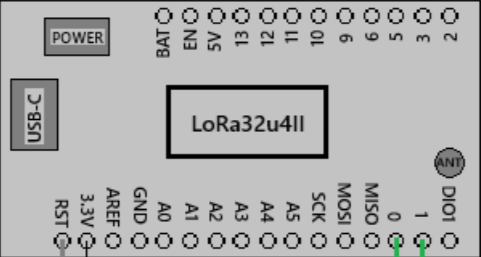
Pin Configuration and Descriptions
| Pin Name | Type | Description |
|---|---|---|
| VIN | Power Input | Input voltage for powering the board (3.7V LiPo or 5V USB). |
| GND | Ground | Ground connection. |
| 3.3V | Power Output | Regulated 3.3V output for external components. |
| A0-A3 | Analog Input | Analog input pins (can also be used as digital GPIO). |
| D0-D1 | Digital I/O | Digital input/output pins. |
| RST | Reset | Resets the microcontroller. |
| SDA | I2C Data | I2C data line for communication with sensors or peripherals. |
| SCL | I2C Clock | I2C clock line for communication with sensors or peripherals. |
| TX | UART TX | UART transmit pin for serial communication. |
| RX | UART RX | UART receive pin for serial communication. |
| ANT | Antenna | Connection point for the LoRa antenna. |
Usage Instructions
How to Use the LoRa32u4II in a Circuit
Powering the Board:
- Connect a 3.7V LiPo battery to the VIN pin or power the board via the USB port (5V).
- Ensure the power source matches the board's voltage requirements to avoid damage.
Connecting the Antenna:
- Attach a compatible LoRa antenna to the ANT connector. This is essential for proper wireless communication.
Programming the Board:
- Use the Arduino IDE to program the LoRa32u4II. Select "Arduino Leonardo" as the board type since it uses the ATmega32U4 microcontroller.
- Install the required libraries for LoRa communication, such as the
LoRalibrary by Sandeep Mistry.
Interfacing with Sensors:
- Use the I2C (SDA, SCL) or analog/digital GPIO pins to connect sensors or peripherals.
- Ensure the connected devices operate at 3.3V logic levels to avoid damaging the board.
Sending and Receiving LoRa Data:
- Use the LoRa module to send and receive data over long distances. Below is an example Arduino sketch for basic LoRa communication.
Example Code: Sending LoRa Data
#include <SPI.h>
#include <LoRa.h>

// Define LoRa parameters
#define LORA_SS 8    // LoRa module's chip select pin
#define LORA_RST 4   // LoRa module's reset pin
#define LORA_DIO0 7  // LoRa module's DIO0 pin

void setup() {
  // Initialize serial communication for debugging
  Serial.begin(9600);
  while (!Serial);

  // Initialize LoRa module
  Serial.println("Initializing LoRa...");
  if (!LoRa.begin(915E6)) { // Set frequency to 915 MHz
    Serial.println("LoRa initialization failed!");
    while (1);
  }
  Serial.println("LoRa initialized successfully.");
}

void loop() {
  // Send a test message
  Serial.println("Sending packet...");
  LoRa.beginPacket();
  LoRa.print("Hello, LoRa!");
  LoRa.endPacket();

  // Wait for 5 seconds before sending the next packet
  delay(5000);
}
Important Considerations and Best Practices
- Antenna Placement: Ensure the antenna is securely connected and positioned away from interference sources for optimal range.
- Power Supply: Use a stable power source to avoid communication issues or unexpected resets.
- Frequency Compliance: Verify that the LoRa frequency (868 MHz or 915 MHz) complies with local regulations.
- Low-Power Mode: Utilize the board's low-power features for battery-powered applications to extend operational life.
Troubleshooting and FAQs
Common Issues and Solutions
LoRa Module Not Initializing:
- Cause: Incorrect wiring or frequency mismatch.
- Solution: Double-check the wiring of the LoRa module (SS, RST, DIO0 pins). Ensure the frequency set in the code matches the module's supported frequency.
No Data Transmission or Reception:
- Cause: Antenna not connected or out of range.
- Solution: Verify the antenna connection and ensure the devices are within the communication range.
Board Not Recognized by Arduino IDE:
- Cause: Missing drivers or incorrect board selection.
- Solution: Install the necessary USB drivers for the ATmega32U4. Select "Arduino Leonardo" as the board type in the Arduino IDE.
High Power Consumption:
- Cause: LoRa module or peripherals not in low-power mode.
- Solution: Implement low-power modes in the code and disconnect unused peripherals.
FAQs
Q1: Can I use the LoRa32u4II with 5V sensors?
A1: No, the LoRa32u4II operates at 3.3V logic levels. Use a level shifter if you need to interface with 5V sensors.
Q2: What is the maximum range of the LoRa32u4II?
A2: The range can reach up to 10 km in line-of-sight conditions. However, obstacles and interference may reduce the range.
Q3: How do I update the firmware on the LoRa32u4II?
A3: You can update the firmware using the Arduino IDE via the USB connection. Ensure the correct board and port are selected.
Q4: Can I use the LoRa32u4II for GPS tracking?
A4: Yes, you can connect a GPS module to the board via UART or I2C and transmit location data using LoRa.
By following this documentation, you can effectively utilize the LoRa32u4II for a wide range of wireless communication projects.