
How to Use RELAY: Examples, Pinouts, and Specs
 Design with RELAY in Cirkit Designer
Introduction
A relay is an electromechanical switch that uses an electromagnetic coil to open or close a circuit. It allows a low-power signal to control high-power devices, making it an essential component in automation, control systems, and power management. Relays are widely used in applications such as home automation, motor control, industrial equipment, and automotive systems.
Common applications include:
- Switching high-current loads like motors, lights, and heaters.
- Isolating control circuits from high-power circuits for safety.
- Implementing logic functions in control systems.
Explore Projects Built with RELAY
 Open Project in Cirkit Designer
 Open Project in Cirkit Designer
 Open Project in Cirkit Designer
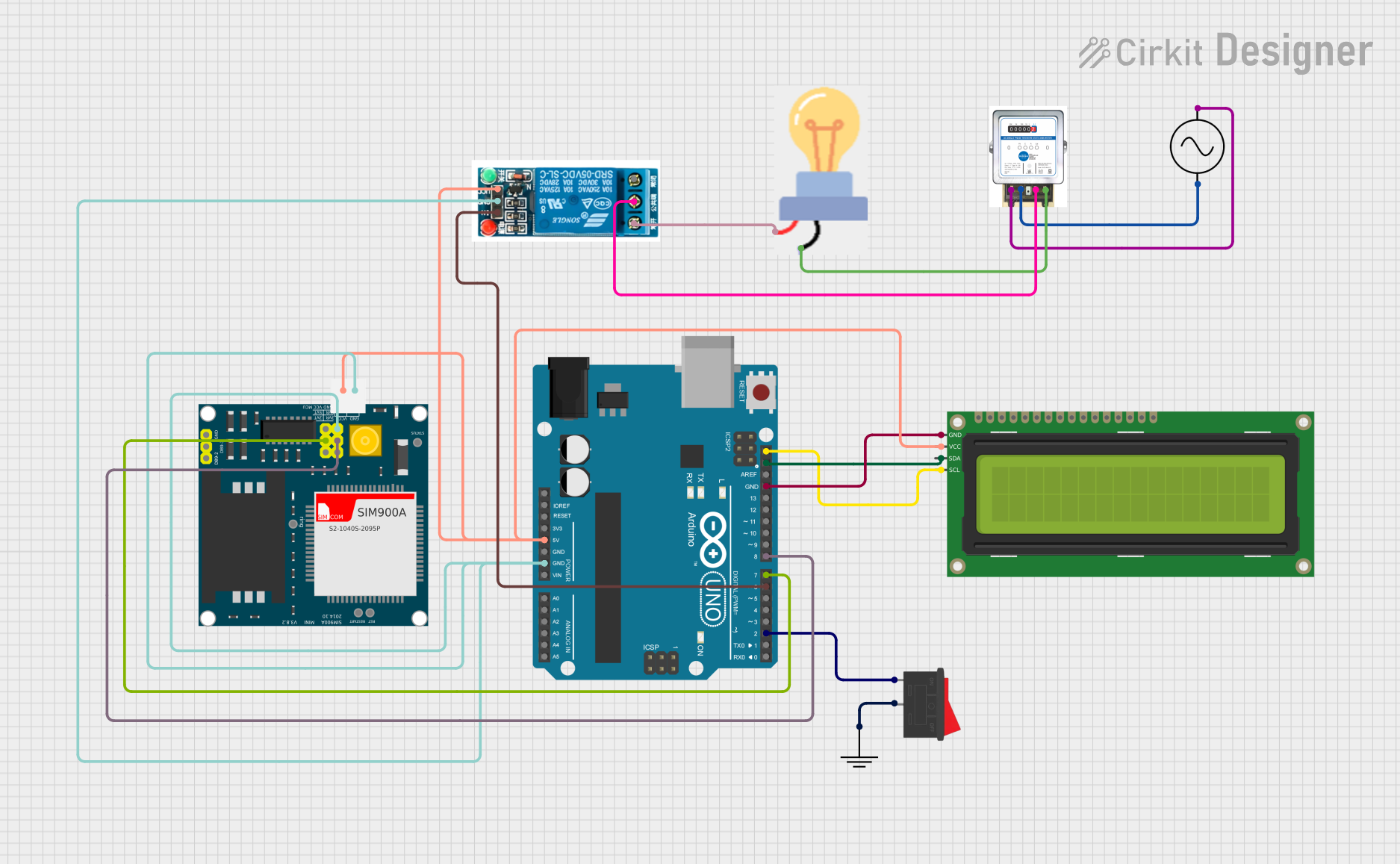 Open Project in Cirkit Designer
Explore Projects Built with RELAY
Open Project in Cirkit DesignerOpen Project in Cirkit DesignerOpen Project in Cirkit DesignerOpen Project in Cirkit DesignerTechnical Specifications
Below are the general technical specifications for a standard single-pole, double-throw (SPDT) relay. Specifications may vary depending on the specific relay model.
Key Technical Details
- Coil Voltage: 5V, 12V, or 24V DC (common options)
- Coil Current: Typically 30-100 mA
- Contact Rating: Up to 10A at 250V AC or 30V DC
- Contact Configuration: SPDT (Single Pole Double Throw) or DPDT (Double Pole Double Throw)
- Switching Time: 5-15 ms (typical)
- Dielectric Strength: 1000V AC (between coil and contacts)
- Insulation Resistance: ≥100 MΩ at 500V DC
Pin Configuration and Descriptions
The pin configuration for a standard SPDT relay is as follows:
| Pin Name | Description |
|---|---|
| Coil (+) | Positive terminal of the electromagnetic coil. |
| Coil (-) | Negative terminal of the electromagnetic coil. |
| Common (COM) | The common terminal connected to the moving part of the switch. |
| Normally Open (NO) | The terminal that is disconnected from COM when the relay is inactive. |
| Normally Closed (NC) | The terminal that is connected to COM when the relay is inactive. |
Usage Instructions
How to Use the Relay in a Circuit
Connect the Coil Terminals:
- Connect the positive terminal of the relay coil to the control signal (e.g., from a microcontroller or transistor).
- Connect the negative terminal of the relay coil to ground.
- If the control signal is from a microcontroller, use a transistor and a flyback diode to protect the circuit from voltage spikes caused by the relay coil.
Connect the Load:
- Connect the high-power device (e.g., motor, light) to the COM and NO terminals if you want the device to turn on when the relay is activated.
- Use the COM and NC terminals if you want the device to turn off when the relay is activated.
Power the Relay:
- Ensure the relay coil voltage matches the control signal voltage (e.g., 5V relay for a 5V control signal).
Test the Circuit:
- Activate the control signal to energize the relay coil and observe the switching action.
Important Considerations and Best Practices
- Always use a flyback diode across the relay coil to prevent voltage spikes from damaging the control circuit.
- Ensure the relay's contact rating matches or exceeds the load's voltage and current requirements.
- Avoid switching loads that exceed the relay's maximum ratings to prevent overheating or damage.
- Use proper insulation and spacing when working with high-voltage circuits.
Example: Connecting a Relay to an Arduino UNO
Below is an example of how to control a relay using an Arduino UNO:
// Example: Controlling a relay with Arduino UNO
// Pin 7 is connected to the relay module's control pin

#define RELAY_PIN 7  // Define the pin connected to the relay module

void setup() {
  pinMode(RELAY_PIN, OUTPUT);  // Set the relay pin as an output
  digitalWrite(RELAY_PIN, LOW);  // Ensure the relay is off initially
}

void loop() {
  digitalWrite(RELAY_PIN, HIGH);  // Turn the relay on
  delay(1000);  // Keep the relay on for 1 second
  digitalWrite(RELAY_PIN, LOW);  // Turn the relay off
  delay(1000);  // Keep the relay off for 1 second
}
Note: Ensure the relay module is compatible with the Arduino's 5V output. Use an external power supply if required.
Troubleshooting and FAQs
Common Issues and Solutions
Relay Not Switching:
- Cause: Insufficient control signal voltage or current.
- Solution: Verify the control signal matches the relay coil's voltage and current requirements.
Voltage Spikes Damaging Circuit:
- Cause: Lack of a flyback diode across the relay coil.
- Solution: Add a diode (e.g., 1N4007) across the coil terminals, with the cathode connected to the positive terminal.
Relay Buzzing or Chattering:
- Cause: Unstable control signal or insufficient power supply.
- Solution: Use a stable power source and ensure the control signal is steady.
Overheating Contacts:
- Cause: Load exceeds the relay's contact rating.
- Solution: Use a relay with a higher contact rating or reduce the load.
FAQs
Q1: Can I use a relay to switch DC and AC loads?
A1: Yes, most relays can switch both DC and AC loads, but ensure the load voltage and current are within the relay's contact ratings.
Q2: Why is a transistor often used with a relay?
A2: Microcontrollers like Arduino cannot supply enough current to directly drive a relay. A transistor acts as a switch to amplify the current.
Q3: What is the purpose of the NO and NC terminals?
A3: The NO terminal is used for devices that should turn on when the relay is activated, while the NC terminal is used for devices that should turn off when the relay is activated.
Q4: Can I use a relay for high-frequency switching?
A4: Relays are not suitable for high-frequency switching due to their mechanical nature. Use solid-state relays or transistors for such applications.