Cirkit Designer Logo
Cirkit Designer
Your all-in-one circuit design IDE
Home / 
Component Documentation

How to Use THERMAL IR: Examples, Pinouts, and Specs

Image of THERMAL IR
Cirkit Designer LogoDesign with THERMAL IR in Cirkit Designer

Introduction

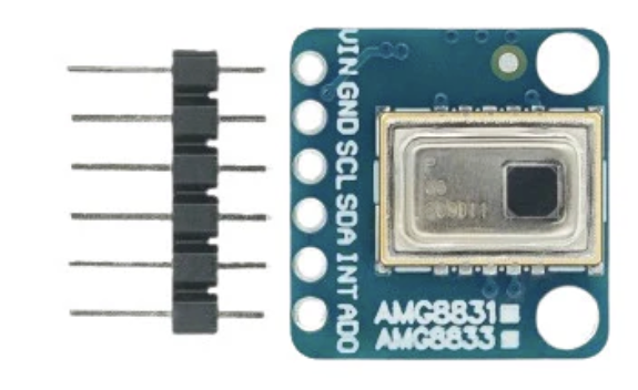
The Adafruit Thermal IR Sensor (Manufacturer Part ID: Thermal IR) is a highly sensitive thermal infrared sensor designed to detect infrared radiation emitted by objects. This allows for accurate temperature measurement and thermal imaging without requiring physical contact. The sensor is ideal for applications where non-contact temperature sensing is critical, such as in industrial automation, medical devices, and environmental monitoring.

Explore Projects Built with THERMAL IR

Use Cirkit Designer to design, explore, and prototype these projects online. Some projects support real-time simulation. Click "Open Project" to start designing instantly!
ESP32C3-Based Thermal Imaging Camera with TFT Display
Image of MLX90640-XIAO-ESP32-1.3: A project utilizing THERMAL IR in a practical application
This circuit connects a 1.3 inch TFT Module 240×240 ST7789 display, a GY-MCU90640 thermal camera module, and a XIAO ESP32C3 microcontroller to create a thermal imaging system. The ESP32C3 microcontroller is programmed to read temperature data from the thermal camera, process it, and display a visual representation of the temperature distribution on the TFT screen. The circuit is designed for applications requiring thermal monitoring, such as detecting heat sources or monitoring temperature variations in an environment.
Cirkit Designer LogoOpen Project in Cirkit Designer
Arduino UNO R4 WiFi-Controlled Thermal Imaging Camera with TFT Display
Image of MLX90640 Thermography Camera by Arduino UNO R4: A project utilizing THERMAL IR in a practical application
This circuit features an Arduino UNO R4 WiFi microcontroller interfaced with a GY-MCU90640 thermal camera and a 1.3 inch TFT display module. The Arduino processes thermal images from the camera and displays the results on the TFT screen. Level shifters are used to match voltage levels between the microcontroller and peripherals, and resistors are likely used for signal conditioning or pull-up/pull-down purposes.
Cirkit Designer LogoOpen Project in Cirkit Designer
ESP32-Based Thermal Monitoring and GSM-Controlled Water Pump System
Image of thermal: A project utilizing THERMAL IR in a practical application
This circuit features an ESP32 microcontroller that interfaces with an Adafruit AMG8833 infrared thermal camera and two NTC analog temperature sensors for temperature monitoring. The ESP32 also communicates with a SIM900A module for cellular connectivity and controls a two-channel relay, which in turn operates a mini diaphragm water pump. The purpose of the circuit is likely for remote temperature monitoring and control of a water pump, possibly for applications like smart irrigation or climate control.
Cirkit Designer LogoOpen Project in Cirkit Designer
Arduino UNO-Based Smart Robotic System with Thermal Printer and Multiple Sensors
Image of scince exhibition 2024: A project utilizing THERMAL IR in a practical application
This circuit is an Arduino-based control system that interfaces with various sensors and actuators, including a thermal printer, multiple micro servos, an inductive sensor, an IR sensor, an RGB LED, and an I2C LCD display. The Arduino UNO reads inputs from the sensors and pushbutton, processes the data, and controls the servos, LED, and printer accordingly, with power supplied by an external power source.
Cirkit Designer LogoOpen Project in Cirkit Designer

Explore Projects Built with THERMAL IR

Use Cirkit Designer to design, explore, and prototype these projects online. Some projects support real-time simulation. Click "Open Project" to start designing instantly!
Image of MLX90640-XIAO-ESP32-1.3: A project utilizing THERMAL IR in a practical application
ESP32C3-Based Thermal Imaging Camera with TFT Display
This circuit connects a 1.3 inch TFT Module 240×240 ST7789 display, a GY-MCU90640 thermal camera module, and a XIAO ESP32C3 microcontroller to create a thermal imaging system. The ESP32C3 microcontroller is programmed to read temperature data from the thermal camera, process it, and display a visual representation of the temperature distribution on the TFT screen. The circuit is designed for applications requiring thermal monitoring, such as detecting heat sources or monitoring temperature variations in an environment.
Cirkit Designer LogoOpen Project in Cirkit Designer
Image of MLX90640 Thermography Camera by Arduino UNO R4: A project utilizing THERMAL IR in a practical application
Arduino UNO R4 WiFi-Controlled Thermal Imaging Camera with TFT Display
This circuit features an Arduino UNO R4 WiFi microcontroller interfaced with a GY-MCU90640 thermal camera and a 1.3 inch TFT display module. The Arduino processes thermal images from the camera and displays the results on the TFT screen. Level shifters are used to match voltage levels between the microcontroller and peripherals, and resistors are likely used for signal conditioning or pull-up/pull-down purposes.
Cirkit Designer LogoOpen Project in Cirkit Designer
Image of thermal: A project utilizing THERMAL IR in a practical application
ESP32-Based Thermal Monitoring and GSM-Controlled Water Pump System
This circuit features an ESP32 microcontroller that interfaces with an Adafruit AMG8833 infrared thermal camera and two NTC analog temperature sensors for temperature monitoring. The ESP32 also communicates with a SIM900A module for cellular connectivity and controls a two-channel relay, which in turn operates a mini diaphragm water pump. The purpose of the circuit is likely for remote temperature monitoring and control of a water pump, possibly for applications like smart irrigation or climate control.
Cirkit Designer LogoOpen Project in Cirkit Designer
Image of scince exhibition 2024: A project utilizing THERMAL IR in a practical application
Arduino UNO-Based Smart Robotic System with Thermal Printer and Multiple Sensors
This circuit is an Arduino-based control system that interfaces with various sensors and actuators, including a thermal printer, multiple micro servos, an inductive sensor, an IR sensor, an RGB LED, and an I2C LCD display. The Arduino UNO reads inputs from the sensors and pushbutton, processes the data, and controls the servos, LED, and printer accordingly, with power supplied by an external power source.
Cirkit Designer LogoOpen Project in Cirkit Designer

Common Applications and Use Cases

  • Non-contact temperature measurement
  • Thermal imaging and heat mapping
  • Human presence detection
  • Industrial process monitoring
  • Medical thermometers and diagnostics
  • Home automation and HVAC systems

Technical Specifications

The Adafruit Thermal IR sensor is designed for precision and ease of use. Below are its key technical details:

Key Technical Details

  • Operating Voltage: 3.3V to 5V DC
  • Communication Protocol: I2C
  • Field of View (FOV): 90° (typical)
  • Temperature Range: -40°C to 300°C (-40°F to 572°F)
  • Accuracy: ±0.5°C (typical, in the range of 0°C to 50°C)
  • Response Time: <1 second
  • Operating Temperature: -40°C to 85°C
  • Dimensions: 20mm x 20mm x 5mm (approx.)

Pin Configuration and Descriptions

The sensor has a simple pinout for easy integration into your projects. Below is the pin configuration:

Pin Name Description
1 VIN Power input (3.3V to 5V DC). Connect to the power supply of your microcontroller.
2 GND Ground. Connect to the ground of your circuit.
3 SDA I2C data line. Connect to the SDA pin of your microcontroller.
4 SCL I2C clock line. Connect to the SCL pin of your microcontroller.

Usage Instructions

The Adafruit Thermal IR sensor is straightforward to use in a variety of applications. Below are the steps and best practices for integrating it into your circuit.

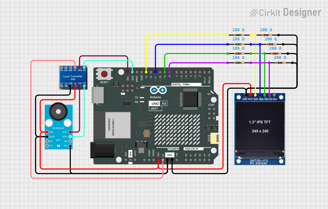
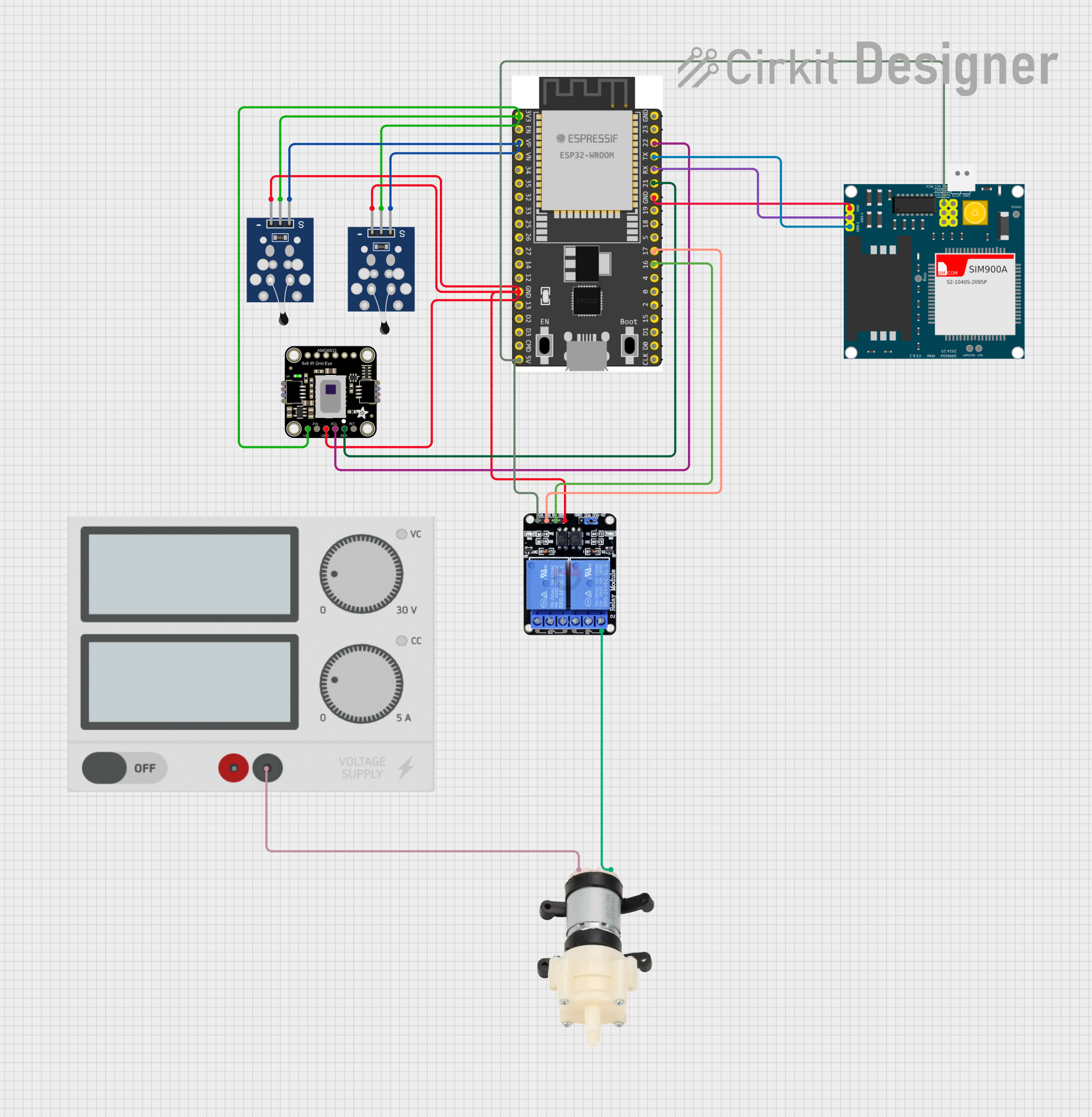
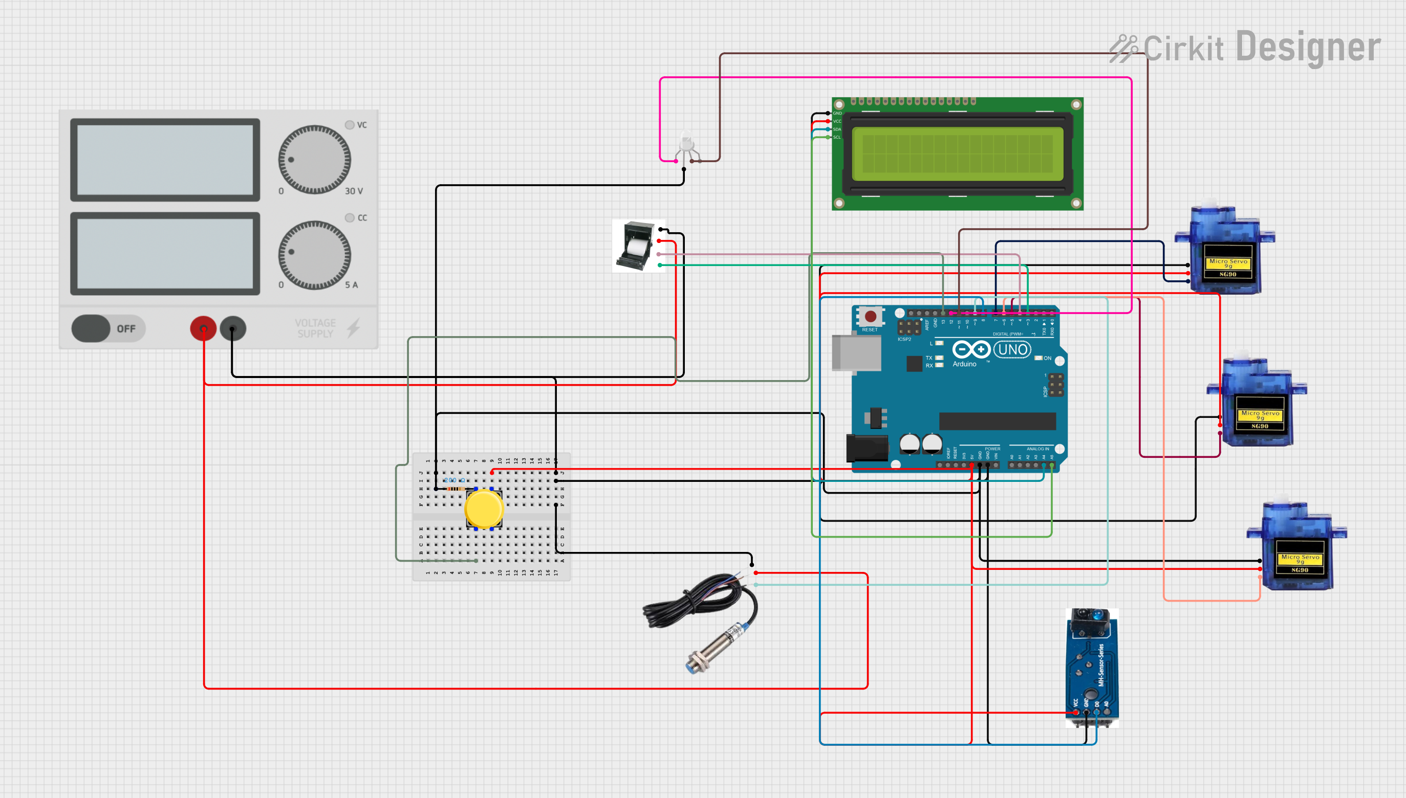
How to Use the Component in a Circuit

  1. Power the Sensor: Connect the VIN pin to a 3.3V or 5V power source and the GND pin to the ground.
  2. Connect I2C Lines: Connect the SDA and SCL pins to the corresponding I2C pins on your microcontroller (e.g., Arduino UNO).
  3. Install Required Libraries: If using an Arduino, install the Adafruit MLX90614 library from the Arduino Library Manager.
  4. Write Code: Use the provided library functions to read temperature data from the sensor.

Important Considerations and Best Practices

  • Ensure proper power supply voltage (3.3V or 5V) to avoid damaging the sensor.
  • Avoid placing the sensor in direct sunlight or near heat sources, as this may affect accuracy.
  • Use pull-up resistors (typically 4.7kΩ) on the SDA and SCL lines if your microcontroller does not have internal pull-ups.
  • Keep the sensor clean and free from dust or debris to maintain optimal performance.

Example Code for Arduino UNO

Below is an example Arduino sketch to read temperature data from the Adafruit Thermal IR sensor:

#include <Wire.h>
#include <Adafruit_MLX90614.h>

// Create an instance of the Adafruit_MLX90614 library
Adafruit_MLX90614 mlx = Adafruit_MLX90614();

void setup() {
  Serial.begin(9600); // Initialize serial communication at 9600 baud
  Serial.println("Adafruit Thermal IR Sensor Test");

  if (!mlx.begin()) {
    Serial.println("Error: Could not find a valid MLX90614 sensor. Check wiring!");
    while (1); // Halt execution if the sensor is not detected
  }
}

void loop() {
  // Read object and ambient temperatures
  double objectTemp = mlx.readObjectTempC(); // Object temperature in Celsius
  double ambientTemp = mlx.readAmbientTempC(); // Ambient temperature in Celsius

  // Print the temperature readings to the Serial Monitor
  Serial.print("Object Temperature: ");
  Serial.print(objectTemp);
  Serial.println(" °C");

  Serial.print("Ambient Temperature: ");
  Serial.print(ambientTemp);
  Serial.println(" °C");

  delay(1000); // Wait 1 second before taking the next reading
}

Troubleshooting and FAQs

Common Issues Users Might Face

  1. Sensor Not Detected:

    • Cause: Incorrect wiring or loose connections.
    • Solution: Double-check the connections, ensuring SDA and SCL are connected to the correct pins on the microcontroller.
  2. Inaccurate Temperature Readings:

    • Cause: Sensor exposed to direct sunlight or heat sources.
    • Solution: Shield the sensor from direct sunlight and ensure it is not near heat-emitting devices.
  3. I2C Communication Errors:

    • Cause: Missing pull-up resistors on SDA and SCL lines.
    • Solution: Add 4.7kΩ pull-up resistors to the SDA and SCL lines if necessary.
  4. No Output on Serial Monitor:

    • Cause: Incorrect baud rate or uninitialized sensor.
    • Solution: Ensure the Serial Monitor is set to 9600 baud and verify that the sensor is properly initialized in the code.

Solutions and Tips for Troubleshooting

  • Use a multimeter to verify the voltage at the VIN pin.
  • Test the I2C connection using an I2C scanner sketch to ensure the sensor is detected.
  • Update the Adafruit MLX90614 library to the latest version to avoid compatibility issues.

By following this documentation, you can effectively integrate and use the Adafruit Thermal IR sensor in your projects.