How to Use Mini I2C Gamepad: Examples, Pinouts, and Specs
Introduction
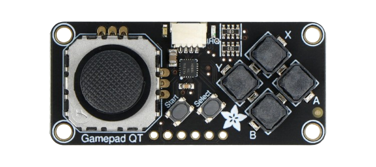
The Mini I2C Gamepad (Manufacturer Part ID: 5743) by Adafruit is a compact and versatile game controller designed for seamless integration with microcontrollers and embedded systems. It communicates using the I2C protocol, making it an excellent choice for gaming projects, robotics, and other interactive applications. The gamepad features a directional pad (D-pad) and additional buttons, providing a simple yet effective interface for user input.
Explore Projects Built with Mini I2C Gamepad


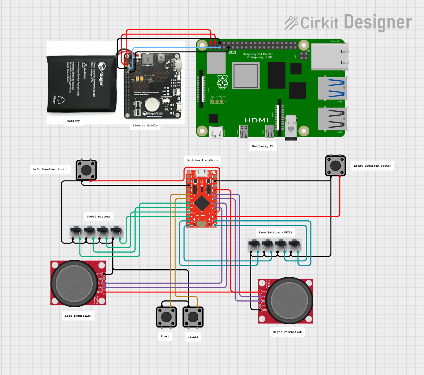
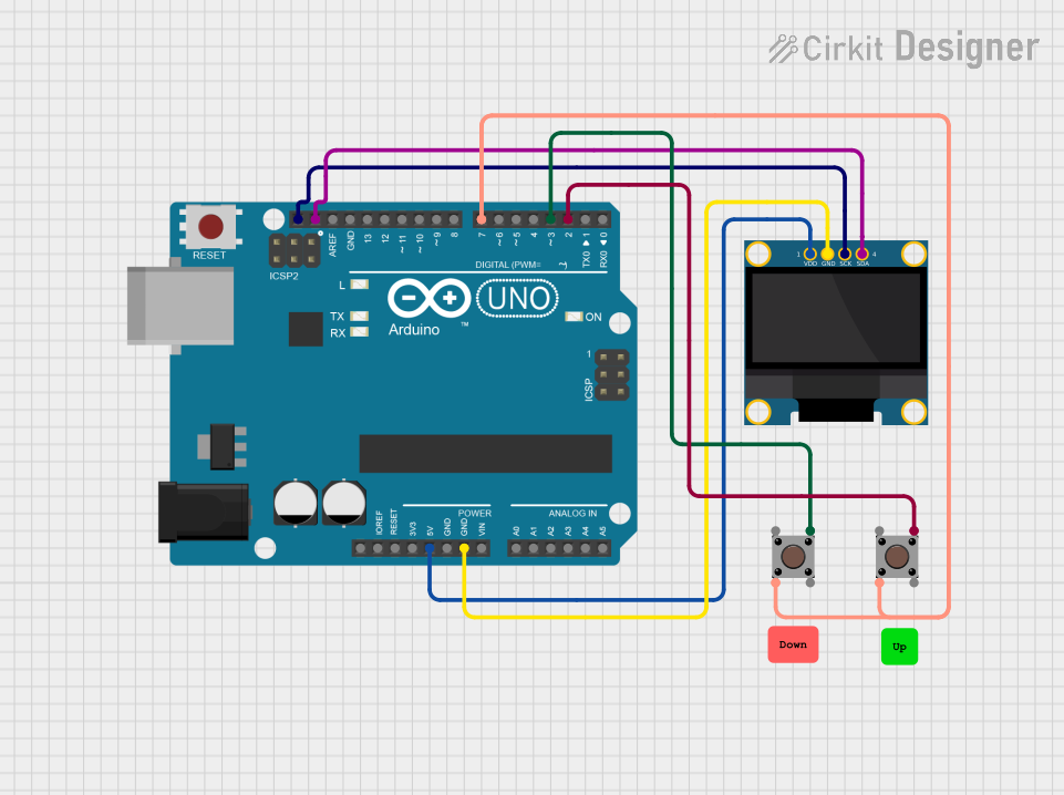
Explore Projects Built with Mini I2C Gamepad
Common Applications and Use Cases
- DIY gaming consoles
- Robotics control systems
- Interactive art installations
- Educational projects for learning I2C communication
- Custom user interfaces for embedded systems
Technical Specifications
The Mini I2C Gamepad is designed to be lightweight and easy to use, with the following key specifications:
| Specification | Details |
|---|---|
| Manufacturer | Adafruit |
| Part ID | 5743 |
| Communication Protocol | I2C |
| Operating Voltage | 3.3V to 5V |
| Current Consumption | ~10mA |
| I2C Address (Default) | 0x5D |
| Buttons | 8 (4 D-pad + 4 additional buttons) |
| Dimensions | 50mm x 30mm x 10mm |
| Weight | ~10g |
Pin Configuration and Descriptions
The Mini I2C Gamepad has a simple 4-pin interface for easy connection to microcontrollers:
| Pin | Name | Description |
|---|---|---|
| 1 | VIN | Power input (3.3V to 5V) |
| 2 | GND | Ground |
| 3 | SDA | I2C data line (connect to microcontroller's SDA pin) |
| 4 | SCL | I2C clock line (connect to microcontroller's SCL pin) |
Usage Instructions
How to Use the Mini I2C Gamepad in a Circuit
- Power the Gamepad: Connect the
VINpin to a 3.3V or 5V power source and theGNDpin to ground. - Connect I2C Lines: Connect the
SDAandSCLpins to the corresponding I2C pins on your microcontroller. - Pull-Up Resistors: Ensure that the I2C lines have pull-up resistors (typically 4.7kΩ). Many microcontroller boards, like the Arduino UNO, already include these resistors.
- Address Configuration: The default I2C address is
0x5D. If you have multiple I2C devices, ensure there are no address conflicts.
Important Considerations and Best Practices
- Voltage Compatibility: The gamepad is compatible with both 3.3V and 5V systems. Ensure your microcontroller operates within this range.
- Debouncing: If you notice erratic button behavior, consider implementing software debouncing in your code.
- I2C Address Conflicts: If you need to use multiple I2C devices, check for address conflicts and modify the gamepad's address if necessary (refer to the Adafruit documentation for advanced configuration).
Example Code for Arduino UNO
Below is an example Arduino sketch to read button states from the Mini I2C Gamepad:
#include <Wire.h> // Include the Wire library for I2C communication

#define GAMEPAD_I2C_ADDRESS 0x5D // Default I2C address of the Mini I2C Gamepad

void setup() {
  Wire.begin(); // Initialize I2C communication
  Serial.begin(9600); // Start serial communication for debugging
  Serial.println("Mini I2C Gamepad Test");
}

void loop() {
  Wire.beginTransmission(GAMEPAD_I2C_ADDRESS); // Start communication with gamepad
  Wire.write(0x00); // Request button state data
  Wire.endTransmission();

  Wire.requestFrom(GAMEPAD_I2C_ADDRESS, 1); // Request 1 byte of data
  if (Wire.available()) {
    uint8_t buttonState = Wire.read(); // Read the button state
    Serial.print("Button State: ");
    Serial.println(buttonState, BIN); // Print the state in binary format
  }

  delay(100); // Small delay to avoid flooding the serial monitor
}
Code Explanation
- The gamepad sends button states as a single byte, where each bit represents a button (1 = pressed, 0 = not pressed).
- The
Wirelibrary is used to communicate with the gamepad over I2C. - The
Serialmonitor displays the button states in binary format for easy debugging.
Troubleshooting and FAQs
Common Issues and Solutions
No Response from the Gamepad
- Cause: Incorrect wiring or I2C address mismatch.
- Solution: Double-check the connections and ensure the I2C address matches
0x5D.
Erratic Button Behavior
- Cause: Electrical noise or lack of debouncing.
- Solution: Implement software debouncing in your code or add capacitors to the button lines.
I2C Communication Errors
- Cause: Missing pull-up resistors on the I2C lines.
- Solution: Ensure 4.7kΩ pull-up resistors are present on the
SDAandSCLlines.
Multiple I2C Devices Not Working
- Cause: Address conflict with another I2C device.
- Solution: Check the addresses of all connected devices and modify as needed.
FAQs
Q: Can I use the Mini I2C Gamepad with a Raspberry Pi?
A: Yes, the gamepad is compatible with any device that supports I2C communication, including Raspberry Pi. Use the appropriate I2C pins and libraries for your platform.
Q: How many buttons can I read from the gamepad?
A: The gamepad has 8 buttons (4 D-pad + 4 additional buttons), all of which can be read via I2C.
Q: Can I change the I2C address of the gamepad?
A: The default address is 0x5D. Refer to the Adafruit documentation for instructions on changing the address if needed.
Q: Is the gamepad compatible with 3.3V systems?
A: Yes, the gamepad works with both 3.3V and 5V systems, making it versatile for various microcontrollers.
By following this documentation, you can easily integrate the Mini I2C Gamepad into your projects and troubleshoot any issues that arise.