
How to Use ESP-201 ESP8266 Wi-Fi Module: Examples, Pinouts, and Specs
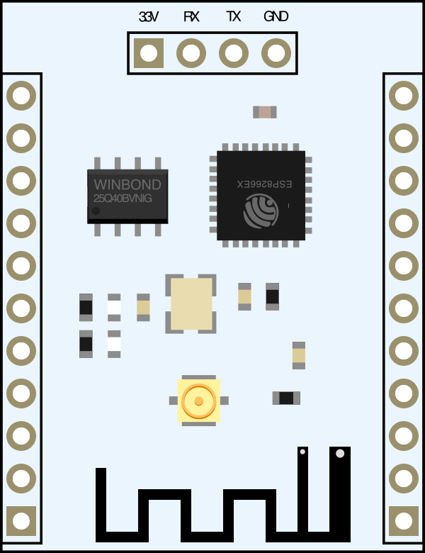
 Design with ESP-201 ESP8266 Wi-Fi Module in Cirkit Designer
Introduction
The ESP-201 ESP8266 Wi-Fi Module is a compact and versatile wireless communication module designed to enable microcontrollers to connect to Wi-Fi networks. It is based on the ESP8266 chip, which integrates a full TCP/IP stack and microcontroller capability. This module is ideal for Internet of Things (IoT) applications, allowing devices to communicate wirelessly over the internet or local networks.
Explore Projects Built with ESP-201 ESP8266 Wi-Fi Module
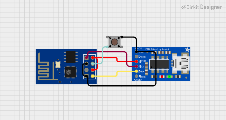 Open Project in Cirkit Designer
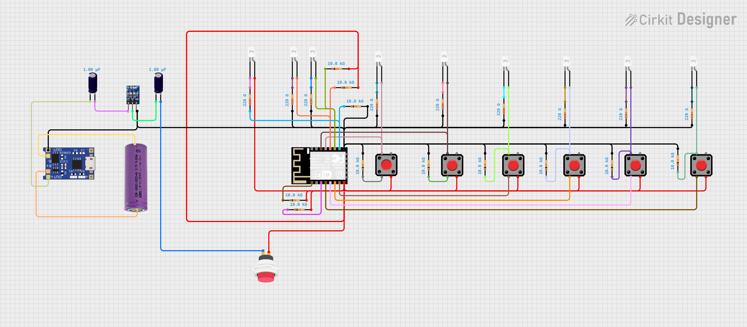 Open Project in Cirkit Designer
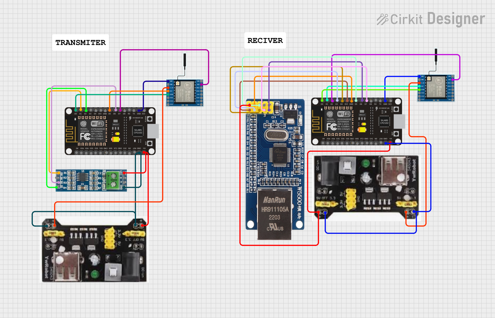 Open Project in Cirkit Designer
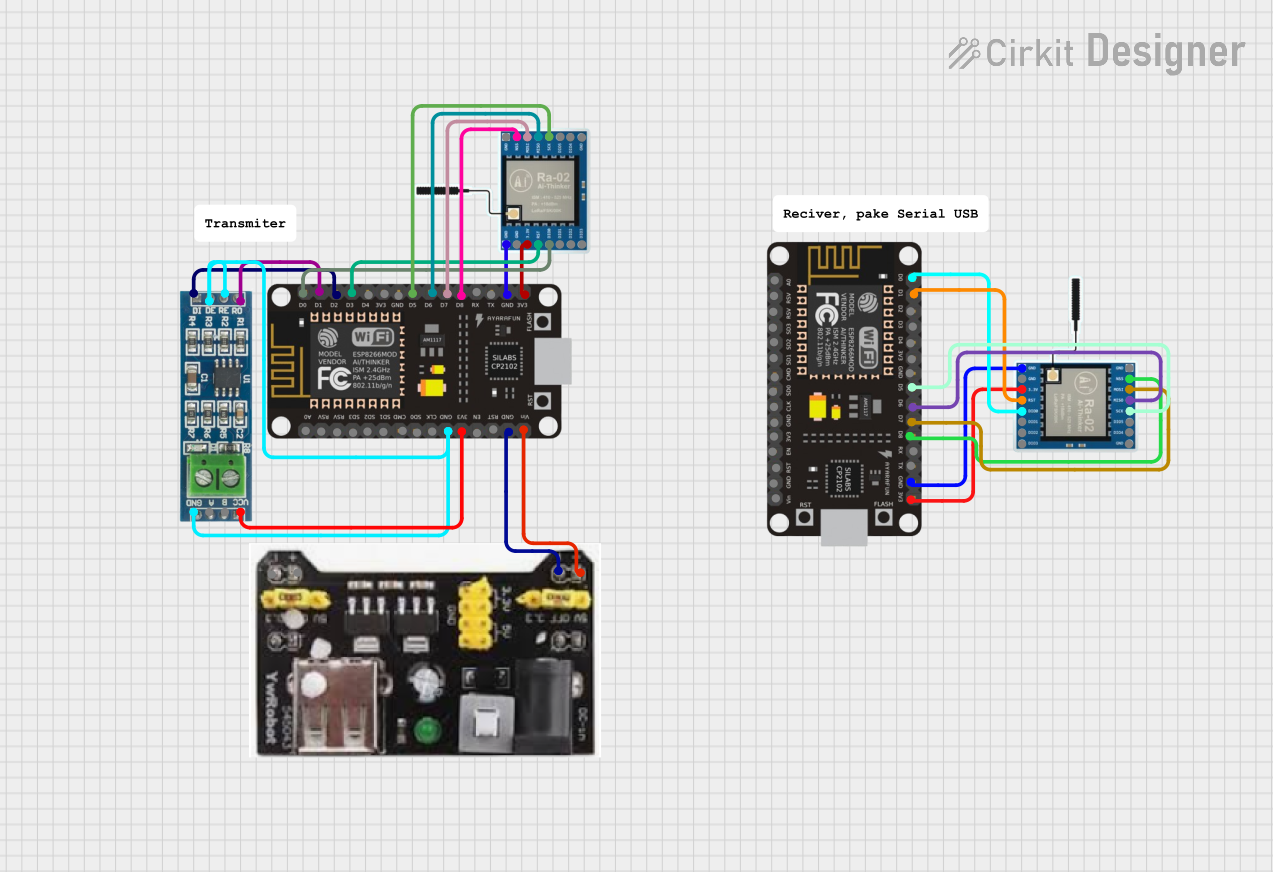 Open Project in Cirkit Designer
Explore Projects Built with ESP-201 ESP8266 Wi-Fi Module
Open Project in Cirkit DesignerOpen Project in Cirkit DesignerOpen Project in Cirkit DesignerOpen Project in Cirkit DesignerCommon Applications and Use Cases
- Home automation systems
- Wireless sensor networks
- IoT devices and smart appliances
- Remote data logging and monitoring
- Wireless control of devices via mobile apps or web interfaces
Technical Specifications
The ESP-201 module offers robust performance and flexibility for a wide range of applications. Below are its key technical details:
Key Technical Details
- Chipset: ESP8266
- Operating Voltage: 3.0V to 3.6V
- Operating Current: ~70mA (average), ~200mA (peak during transmission)
- Wi-Fi Standards: IEEE 802.11 b/g/n
- Frequency Range: 2.4 GHz
- Flash Memory: 4 MB (32 Mbit)
- GPIO Pins: 11 (General Purpose Input/Output)
- Communication Protocols: UART, SPI, I2C
- Antenna: External antenna connector (U.FL) and onboard PCB antenna
- Dimensions: 24mm x 16mm
Pin Configuration and Descriptions
The ESP-201 module has 16 pins, each serving a specific function. Below is the pinout description:
| Pin Number | Pin Name | Description |
|---|---|---|
| 1 | GND | Ground connection |
| 2 | GPIO0 | General-purpose I/O pin; used for boot mode selection during startup |
| 3 | GPIO2 | General-purpose I/O pin |
| 4 | GPIO4 | General-purpose I/O pin |
| 5 | GPIO5 | General-purpose I/O pin |
| 6 | RXD | UART Receive pin (for serial communication) |
| 7 | TXD | UART Transmit pin (for serial communication) |
| 8 | CH_PD | Chip enable pin; must be pulled high for normal operation |
| 9 | VCC | Power supply input (3.3V) |
| 10 | RST | Reset pin; active low |
| 11 | GPIO12 | General-purpose I/O pin |
| 12 | GPIO13 | General-purpose I/O pin |
| 13 | GPIO14 | General-purpose I/O pin |
| 14 | GPIO15 | General-purpose I/O pin; must be pulled low for normal boot |
| 15 | GPIO16 | General-purpose I/O pin |
| 16 | ANT | External antenna connector (U.FL) |
Usage Instructions
The ESP-201 module can be integrated into a circuit to enable Wi-Fi connectivity for microcontrollers. Below are the steps and best practices for using the module:
How to Use the ESP-201 in a Circuit
- Power Supply: Connect the VCC pin to a stable 3.3V power source. Do not exceed 3.6V, as this may damage the module.
- Ground Connection: Connect the GND pin to the ground of your circuit.
- Enable the Module: Pull the CH_PD pin high (connect it to 3.3V) to enable the module.
- UART Communication: Connect the RXD and TXD pins to the TX and RX pins of your microcontroller, respectively, for serial communication.
- Boot Mode Selection:
- Pull GPIO0 low (connect to GND) to enter firmware flashing mode.
- Pull GPIO0 high (connect to 3.3V) for normal operation.
- Antenna Selection: Use the onboard PCB antenna or connect an external antenna to the U.FL connector for better range.
Important Considerations and Best Practices
- Use a level shifter or voltage divider if interfacing with a 5V microcontroller, as the ESP-201 operates at 3.3V logic levels.
- Add a decoupling capacitor (e.g., 10µF) near the VCC pin to stabilize the power supply.
- Ensure proper grounding to avoid noise and interference in the Wi-Fi signal.
- Use a dedicated 3.3V power regulator capable of supplying at least 300mA to handle the module's peak current requirements.
Example: Connecting to an Arduino UNO
Below is an example of how to connect the ESP-201 module to an Arduino UNO and send AT commands to connect to a Wi-Fi network.
Wiring Diagram
- ESP-201 VCC → 3.3V on Arduino (via external 3.3V regulator)
- ESP-201 GND → GND on Arduino
- ESP-201 RXD → Arduino TX (via voltage divider: 1kΩ and 2kΩ resistors)
- ESP-201 TXD → Arduino RX
- ESP-201 CH_PD → 3.3V
- ESP-201 GPIO0 → 3.3V (normal mode)
Arduino Code
#include <SoftwareSerial.h>

// Define RX and TX pins for SoftwareSerial
SoftwareSerial espSerial(2, 3); // RX = Pin 2, TX = Pin 3

void setup() {
  Serial.begin(9600); // Start Serial Monitor at 9600 baud
  espSerial.begin(9600); // Start ESP-201 communication at 9600 baud

  Serial.println("Initializing ESP-201...");
  delay(2000);

  // Send AT command to test communication
  espSerial.println("AT");
  delay(1000);
  while (espSerial.available()) {
    Serial.write(espSerial.read()); // Print ESP-201 response to Serial Monitor
  }

  // Connect to Wi-Fi network
  espSerial.println("AT+CWJAP=\"YourSSID\",\"YourPassword\"");
  delay(5000);
  while (espSerial.available()) {
    Serial.write(espSerial.read()); // Print connection response
  }
}

void loop() {
  // Add your main code here
}
Troubleshooting and FAQs
Common Issues and Solutions
Module Not Responding to AT Commands:
- Ensure the CH_PD pin is pulled high.
- Verify the RX and TX connections between the ESP-201 and the microcontroller.
- Check the baud rate (default is 9600).
Wi-Fi Connection Fails:
- Double-check the SSID and password in the AT+CWJAP command.
- Ensure the Wi-Fi network is within range and supports 2.4 GHz.
Module Overheating:
- Verify that the power supply is stable and does not exceed 3.6V.
- Use a heat sink or ensure proper ventilation if the module is used in a high-temperature environment.
Unstable Communication:
- Add decoupling capacitors near the power pins.
- Use shielded cables for UART connections to reduce noise.
FAQs
Q: Can the ESP-201 work with 5V microcontrollers?
- A: Yes, but you must use a level shifter or voltage divider for the RXD pin to avoid damaging the module.
Q: How do I flash new firmware to the ESP-201?
- A: Pull GPIO0 low during power-up to enter flashing mode, then use a USB-to-serial adapter and flashing software like ESP8266Flasher.
Q: What is the maximum Wi-Fi range of the ESP-201?
- A: The range depends on the antenna used. With the onboard PCB antenna, it can reach up to 100 meters in open space.
This documentation provides a comprehensive guide to using the ESP-201 ESP8266 Wi-Fi Module effectively.