How to Use LCD Display 7 inch Rev 3.5 800x480 Pixel: Examples, Pinouts, and Specs
Introduction
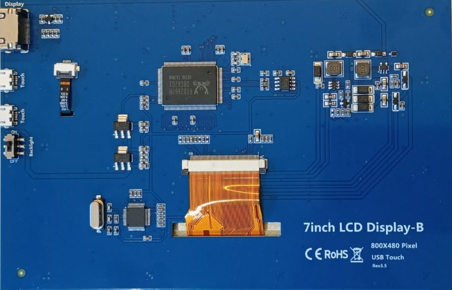
The TRU Components 7-inch LCD Display-B is a high-quality liquid crystal display designed for a wide range of applications. With a resolution of 800x480 pixels, this display delivers sharp and vibrant visuals, making it ideal for embedded systems, graphical user interfaces, industrial control panels, and multimedia devices. Its touch capability (if supported by the specific model) further enhances interactivity, making it a versatile choice for modern electronic projects.
Explore Projects Built with LCD Display 7 inch Rev 3.5 800x480 Pixel


Explore Projects Built with LCD Display 7 inch Rev 3.5 800x480 Pixel
Common Applications
- Embedded systems and microcontroller-based projects
- Industrial control panels and automation systems
- Home automation and IoT devices
- Multimedia and entertainment systems
- Prototyping graphical user interfaces
Technical Specifications
Key Specifications
| Parameter | Value |
|---|---|
| Manufacturer | TRU Components |
| Part ID | 7inch LCD Display-B |
| Display Size | 7 inches |
| Resolution | 800x480 pixels (WVGA) |
| Display Type | TFT LCD |
| Aspect Ratio | 16:9 |
| Interface | Parallel RGB / HDMI (varies) |
| Backlight | LED |
| Operating Voltage | 3.3V / 5V (depending on model) |
| Touch Capability | Optional (capacitive/resistive) |
| Operating Temperature | -20°C to +70°C |
| Dimensions | 164.9mm x 100.0mm x 5.7mm |
Pin Configuration
The pin configuration may vary depending on the interface used (e.g., parallel RGB or HDMI). Below is an example of a parallel RGB interface pinout:
| Pin Number | Pin Name | Description |
|---|---|---|
| 1 | VCC | Power supply (3.3V or 5V) |
| 2 | GND | Ground |
| 3 | HSYNC | Horizontal sync signal |
| 4 | VSYNC | Vertical sync signal |
| 5 | DE | Data enable signal |
| 6-21 | RGB[0:15] | RGB data lines (5 bits each for R, G, B) |
| 22 | CLK | Pixel clock |
| 23 | BL_VCC | Backlight power supply |
| 24 | BL_PWM | Backlight brightness control (PWM) |
| 25 | BL_GND | Backlight ground |
For HDMI-based models, refer to the manufacturer's datasheet for the specific pinout.
Usage Instructions
Connecting the Display
- Power Supply: Ensure the display is powered with the correct voltage (3.3V or 5V). Use a regulated power source to avoid damage.
- Interface Selection: Determine the interface type (e.g., parallel RGB or HDMI) and connect the corresponding pins to your microcontroller or development board.
- Backlight Control: Connect the backlight power (BL_VCC) and ground (BL_GND). Use the BL_PWM pin to adjust brightness via a PWM signal.
- Data Signals: For parallel RGB, connect the RGB data lines, HSYNC, VSYNC, DE, and CLK to the appropriate pins on your controller. For HDMI, use an HDMI cable.
- Touch Interface: If the display includes touch functionality, connect the touch controller pins (refer to the datasheet) to your microcontroller.
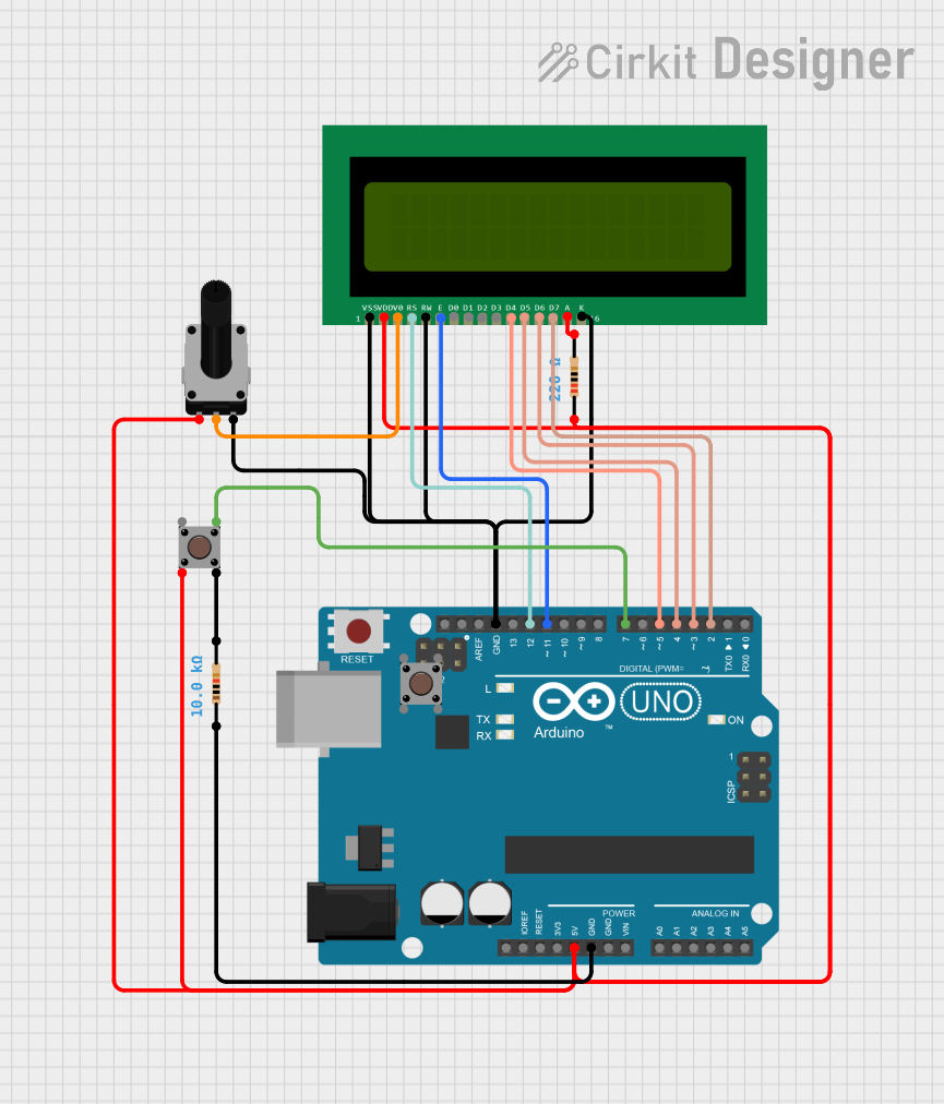
Example: Using with Arduino UNO
To use the display with an Arduino UNO, you may need an external driver board or shield to handle the parallel RGB or HDMI interface. Below is an example of initializing the display using an external driver board:
#include <Adafruit_GFX.h>    // Graphics library for displays
#include <Adafruit_TFTLCD.h> // Library for TFT LCD displays

// Define pin connections for the display
#define LCD_CS A3  // Chip Select
#define LCD_CD A2  // Command/Data
#define LCD_WR A1  // LCD Write
#define LCD_RD A0  // LCD Read
#define LCD_RESET A4 // Reset

// Initialize the display object
Adafruit_TFTLCD tft(LCD_CS, LCD_CD, LCD_WR, LCD_RD, LCD_RESET);

void setup() {
  tft.reset(); // Reset the display
  tft.begin(0x9341); // Initialize with the display driver ID (example: ILI9341)

  // Set up the display
  tft.fillScreen(0x0000); // Clear the screen (black)
  tft.setTextColor(0xFFFF); // Set text color to white
  tft.setTextSize(2); // Set text size
  tft.setCursor(10, 10); // Set cursor position
  tft.println("Hello, World!"); // Display text
}

void loop() {
  // Add your code here to update the display
}
Note: Replace
0x9341with the correct driver ID for your display. Refer to the datasheet or driver board documentation for details.
Best Practices
- Use decoupling capacitors near the power pins to reduce noise.
- Avoid exceeding the maximum voltage and current ratings.
- Handle the display carefully to avoid damaging the glass or flex cable.
- If using a touch interface, ensure proper grounding to avoid interference.
Troubleshooting and FAQs
Common Issues
No Display Output:
- Verify the power supply voltage and connections.
- Check the data signal connections and ensure they match the interface type.
- Confirm the display driver initialization in your code.
Flickering or Dim Backlight:
- Ensure the backlight power (BL_VCC) is connected properly.
- Adjust the PWM signal on the BL_PWM pin for brightness control.
Touch Not Responding:
- Verify the touch controller connections.
- Check if the touch driver is correctly initialized in your code.
Incorrect Colors or Distorted Image:
- Ensure the RGB data lines are connected in the correct order.
- Verify the pixel clock (CLK) frequency matches the display requirements.
FAQs
Q: Can this display be used with Raspberry Pi?
A: Yes, the display can be used with Raspberry Pi via the HDMI interface or with a compatible driver board for parallel RGB.
Q: Does this display support capacitive touch?
A: Some models of the 7-inch LCD Display-B support capacitive touch. Check the specific part number and datasheet for details.
Q: What is the typical power consumption of the display?
A: The power consumption depends on the backlight brightness and operating conditions. Refer to the datasheet for detailed power specifications.
Q: Can I use this display outdoors?
A: The display is rated for an operating temperature range of -20°C to +70°C. However, direct sunlight may affect visibility unless the display has a high-brightness or anti-glare coating.
For additional support, refer to the TRU Components datasheet or contact technical support.