How to Use Gear Motor with integrated Encoder: Examples, Pinouts, and Specs

Introduction
The Gear Motor with Integrated Encoder by Naroote is a versatile and efficient component that combines a motor, a gearbox, and an encoder into a single unit. This design allows for precise control of speed, torque, and position, making it an ideal choice for applications requiring accurate motion control. The integrated encoder provides real-time feedback on the motor's rotation, enabling closed-loop control systems for enhanced performance.
Explore Projects Built with Gear Motor with integrated Encoder

Explore Projects Built with Gear Motor with integrated Encoder
Common Applications
- Robotics and automation systems
- Conveyor belts and industrial machinery
- Precision positioning systems
- Automated guided vehicles (AGVs)
- DIY projects involving motion control
Technical Specifications
Key Specifications
| Parameter | Value |
|---|---|
| Operating Voltage | 6V - 12V |
| Rated Current | 0.5A - 1.2A (depending on load) |
| Gear Ratio | 1:30 |
| Encoder Resolution | 11 pulses per revolution (PPR) |
| Maximum Torque | 2.5 kg·cm (at 12V) |
| No-Load Speed | 200 RPM (at 12V) |
| Shaft Diameter | 6 mm |
| Motor Dimensions | 55 mm x 32 mm x 25 mm |
| Weight | 120 g |
Pin Configuration
The gear motor with an integrated encoder typically has a 6-pin interface. Below is the pinout description:
| Pin Number | Label | Description |
|---|---|---|
| 1 | Motor+ | Positive terminal for the motor power supply |
| 2 | Motor- | Negative terminal for the motor power supply |
| 3 | Encoder A | Channel A output of the encoder |
| 4 | Encoder B | Channel B output of the encoder |
| 5 | VCC | Power supply for the encoder (5V) |
| 6 | GND | Ground connection for the encoder |
Usage Instructions
How to Use the Component in a Circuit
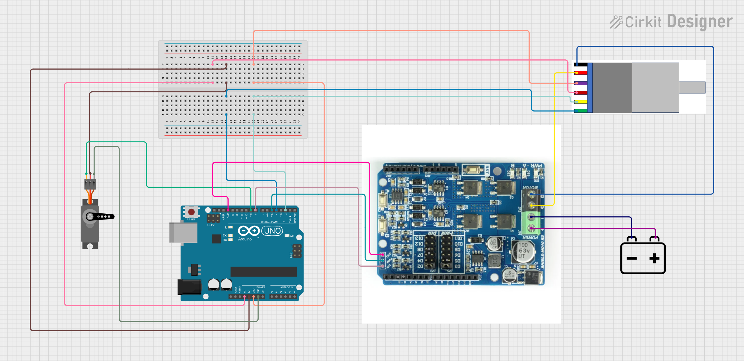
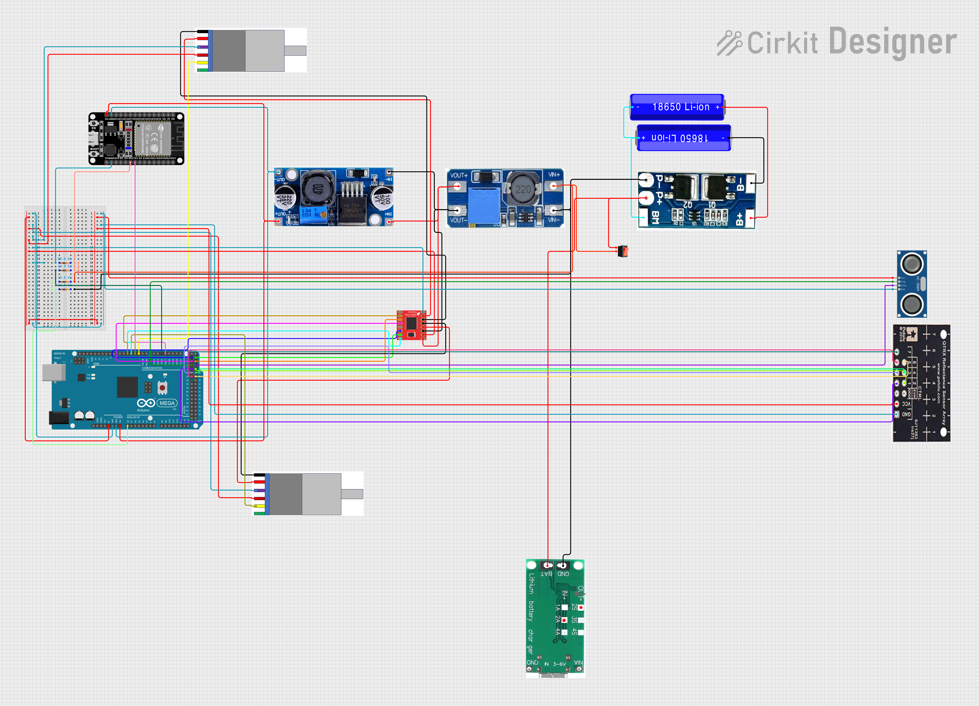
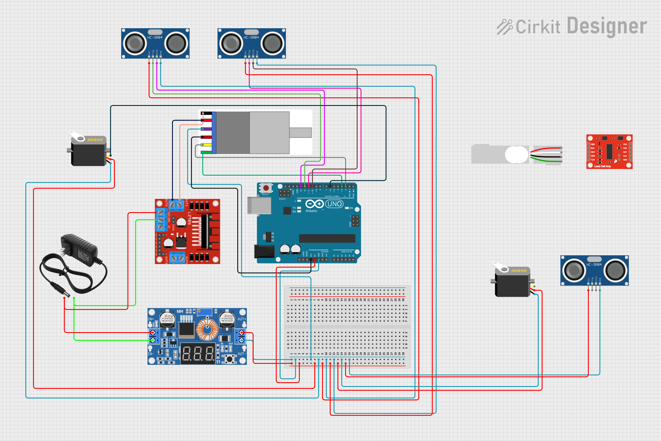
- Powering the Motor: Connect the
Motor+andMotor-pins to a motor driver or H-bridge circuit. Ensure the power supply matches the motor's operating voltage (6V - 12V). - Connecting the Encoder:
- Provide a 5V power supply to the
VCCpin and connect theGNDpin to the ground. - Connect the
Encoder AandEncoder Bpins to the microcontroller's digital input pins to read the encoder signals.
- Provide a 5V power supply to the
- Controlling the Motor:
- Use a motor driver or H-bridge to control the motor's speed and direction.
- Read the encoder signals to monitor the motor's rotation and implement closed-loop control.
Important Considerations
- Power Supply: Ensure the motor and encoder are powered within their specified voltage ranges to avoid damage.
- Signal Noise: Use pull-up resistors on the encoder pins if the signal is noisy or unstable.
- Mounting: Secure the motor properly to prevent vibrations that could affect encoder readings.
- Direction Control: The encoder outputs can help determine the motor's rotation direction by analyzing the phase difference between
Encoder AandEncoder B.
Example Code for Arduino UNO
Below is an example of how to interface the gear motor with an integrated encoder to an Arduino UNO for basic speed and direction monitoring:
// Define encoder pins
const int encoderA = 2; // Connect Encoder A to digital pin 2
const int encoderB = 3; // Connect Encoder B to digital pin 3

volatile int encoderCount = 0; // Variable to store encoder counts
int lastEncoded = 0;           // Variable to store the last encoder state

void setup() {
  pinMode(encoderA, INPUT); // Set Encoder A pin as input
  pinMode(encoderB, INPUT); // Set Encoder B pin as input

  // Attach interrupts to encoder pins
  attachInterrupt(digitalPinToInterrupt(encoderA), updateEncoder, CHANGE);
  attachInterrupt(digitalPinToInterrupt(encoderB), updateEncoder, CHANGE);

  Serial.begin(9600); // Initialize serial communication
}

void loop() {
  // Print the encoder count to the Serial Monitor
  Serial.print("Encoder Count: ");
  Serial.println(encoderCount);
  delay(100); // Delay for readability
}

// Interrupt service routine to update encoder count
void updateEncoder() {
  int MSB = digitalRead(encoderA); // Read the state of Encoder A
  int LSB = digitalRead(encoderB); // Read the state of Encoder B

  int encoded = (MSB << 1) | LSB;  // Combine the two states into a single value
  int sum = (lastEncoded << 2) | encoded; // Track the state transition

  // Update encoder count based on the state transition
  if (sum == 0b1101 || sum == 0b0100 || sum == 0b0010 || sum == 0b1011) {
    encoderCount++;
  } else if (sum == 0b1110 || sum == 0b0111 || sum == 0b0001 || sum == 0b1000) {
    encoderCount--;
  }

  lastEncoded = encoded; // Update the last encoded state
}
Notes:
- Ensure the encoder pins (
Encoder AandEncoder B) are connected to interrupt-capable pins on the Arduino (e.g., pins 2 and 3 on the UNO). - The code above tracks the encoder count, which can be used to calculate speed or position.
Troubleshooting and FAQs
Common Issues and Solutions
- Motor Not Spinning:
- Check the power supply connections to the motor.
- Verify that the motor driver or H-bridge is functioning correctly.
- Encoder Not Providing Output:
- Ensure the encoder is powered (5V to
VCCandGNDconnected). - Check the connections to
Encoder AandEncoder Bpins. - Use a multimeter or oscilloscope to verify the encoder signals.
- Ensure the encoder is powered (5V to
- Inaccurate Encoder Readings:
- Add pull-up resistors to the encoder pins if the signal is noisy.
- Ensure the motor is securely mounted to minimize vibrations.
- Overheating:
- Verify that the motor is not overloaded beyond its torque rating.
- Use a heat sink or cooling mechanism if necessary.
FAQs
Q1: Can I use this motor with a 3.3V microcontroller?
A1: Yes, but you will need a level shifter to convert the encoder's 5V signals to 3.3V.
Q2: How do I calculate the motor's speed using the encoder?
A2: Measure the time between encoder pulses and use the formula:
Speed (RPM) = (Pulses per second / Encoder PPR) * 60.
Q3: Can I reverse the motor's direction?
A3: Yes, reverse the polarity of the Motor+ and Motor- connections or use an H-bridge circuit.
Q4: What is the purpose of the gear ratio?
A4: The gear ratio increases torque while reducing speed, making the motor suitable for high-torque applications.