How to Use Thermostat STC1000: Examples, Pinouts, and Specs
Introduction
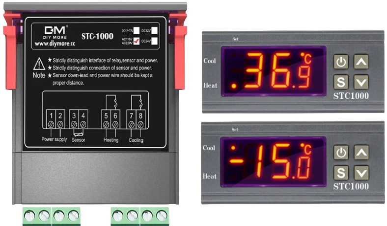
The STC1000 is a versatile digital temperature controller manufactured by X (Part ID: 1). It is designed for precise temperature regulation in both heating and cooling applications. Equipped with a dual relay output, the STC1000 can control heating and cooling devices simultaneously, making it ideal for a wide range of temperature-sensitive environments. Its user-friendly interface allows for easy configuration of temperature thresholds and hysteresis settings.
Explore Projects Built with Thermostat STC1000


Explore Projects Built with Thermostat STC1000
Common Applications
- Homebrewing and fermentation temperature control
- Aquarium temperature regulation
- Incubators for eggs or reptiles
- HVAC systems
- Greenhouse climate management
Technical Specifications
Key Technical Details
| Parameter | Specification |
|---|---|
| Operating Voltage | AC 110V-220V ±10% |
| Temperature Range | -50°C to 99°C (-58°F to 210°F) |
| Temperature Accuracy | ±1°C |
| Sensor Type | NTC (10kΩ) Thermistor |
| Relay Output Capacity | Heating: 10A/220V AC |
| Cooling: 10A/220V AC | |
| Power Consumption | ≤3W |
| Operating Temperature | -10°C to 60°C |
| Storage Temperature | -20°C to 75°C |
| Dimensions | 75mm x 34.5mm x 85mm |
Pin Configuration and Descriptions
The STC1000 has a total of 8 terminals for wiring. Below is the pin configuration:
| Terminal Number | Description |
|---|---|
| 1 | Power Input (Live/Hot Line) |
| 2 | Power Input (Neutral Line) |
| 3 | Cooling Device Output (Live) |
| 4 | Cooling Device Output (Neutral) |
| 5 | Heating Device Output (Live) |
| 6 | Heating Device Output (Neutral) |
| 7 | Temperature Sensor Input (NTC Sensor) |
| 8 | Temperature Sensor Input (NTC Sensor) |
Usage Instructions
How to Use the STC1000 in a Circuit
- Wiring the Power Supply: Connect terminals 1 and 2 to the AC power source (110V-220V). Ensure proper polarity.
- Connecting the Heating and Cooling Devices:
- Connect the live wire of the cooling device to terminal 3 and the neutral wire to terminal 4.
- Connect the live wire of the heating device to terminal 5 and the neutral wire to terminal 6.
- Connecting the Temperature Sensor:
- Attach the NTC sensor wires to terminals 7 and 8. Ensure the sensor is placed in the environment where temperature control is required.
- Configuring the Temperature Settings:
- Power on the STC1000.
- Use the front panel buttons to set the desired temperature range and hysteresis (temperature difference for switching).
- Refer to the user manual for detailed button operations.
Important Considerations and Best Practices
- Ensure all connections are secure and insulated to prevent electrical hazards.
- Place the NTC sensor in a location that accurately represents the environment's temperature.
- Avoid exposing the STC1000 to moisture or extreme conditions beyond its operating range.
- Use appropriate fuses or circuit breakers to protect the connected devices and the STC1000.
- For high-power devices, consider using external relays to handle the load safely.
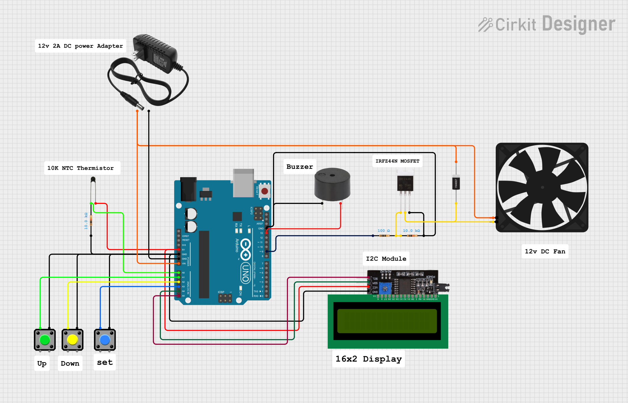
Example: Using the STC1000 with an Arduino UNO
The STC1000 can be used alongside an Arduino UNO for advanced temperature monitoring and logging. Below is an example code snippet to read the temperature from the NTC sensor connected to the STC1000:
// Example code to read temperature from the STC1000's NTC sensor
// and display it on the Serial Monitor.

const int sensorPin = A0; // Analog pin connected to the NTC sensor
float resistance;         // Variable to store sensor resistance
float temperature;        // Variable to store calculated temperature

void setup() {
  Serial.begin(9600); // Initialize serial communication
}

void loop() {
  int sensorValue = analogRead(sensorPin); // Read analog value from sensor
  resistance = (1023.0 / sensorValue - 1) * 10000;
  // Convert analog value to resistance (assuming 10k pull-up resistor)

  // Calculate temperature using the Steinhart-Hart equation
  float steinhart;
  steinhart = resistance / 10000.0; // (R/Ro)
  steinhart = log(steinhart);       // ln(R/Ro)
  steinhart /= 3950.0;              // 1/B * ln(R/Ro)
  steinhart += 1.0 / (25.0 + 273.15); // + (1/To)
  steinhart = 1.0 / steinhart;      // Invert
  temperature = steinhart - 273.15; // Convert to Celsius

  Serial.print("Temperature: ");
  Serial.print(temperature);
  Serial.println(" °C");

  delay(1000); // Wait 1 second before next reading
}
Notes:
- The above code assumes the NTC sensor is connected to the Arduino via a voltage divider circuit.
- Modify the
3950constant in the code to match the Beta value of your NTC sensor if it differs.
Troubleshooting and FAQs
Common Issues and Solutions
STC1000 Does Not Power On:
- Check the power supply voltage and connections to terminals 1 and 2.
- Ensure the power source is within the specified range (110V-220V).
Temperature Readings Are Inaccurate:
- Verify the NTC sensor is properly connected to terminals 7 and 8.
- Ensure the sensor is placed in an appropriate location for accurate readings.
- Check for damage to the sensor or its wiring.
Heating or Cooling Devices Do Not Activate:
- Confirm the devices are correctly wired to the output terminals (3-6).
- Check the temperature settings and hysteresis configuration.
- Ensure the devices are functional and within the relay's power rating.
Relay Clicking Noise:
- This is normal when the relay switches between heating and cooling modes.
- If the noise is excessive, check for loose connections or high current loads.
FAQs
Can the STC1000 be used with DC devices? No, the STC1000 is designed for AC devices only. For DC applications, use a compatible DC relay module.
What is the maximum cable length for the NTC sensor? The sensor cable can typically be extended up to 10 meters, but ensure proper shielding to avoid interference.
Can I use the STC1000 outdoors? The STC1000 is not waterproof. Use it in a dry, indoor environment or within a weatherproof enclosure.
How do I reset the STC1000 to factory settings? Refer to the user manual for the reset procedure, which typically involves holding specific buttons during power-up.
This concludes the documentation for the Thermostat STC1000. For further assistance, consult the manufacturer's user manual or contact technical support.