
How to Use crsf: Examples, Pinouts, and Specs
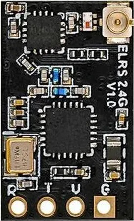
 Design with crsf in Cirkit Designer
Introduction
CRSF (Crossfire) is a long-range, low-latency radio control system designed for remote-controlled aircraft and drones. It ensures reliable communication between the transmitter and receiver, even in challenging environments. Known for its robust signal strength and minimal latency, CRSF is widely used in FPV (First Person View) drones, UAVs, and other RC applications where precision and reliability are critical.
Explore Projects Built with crsf
 Open Project in Cirkit Designer
 Open Project in Cirkit Designer
 Open Project in Cirkit Designer
 Open Project in Cirkit Designer
Explore Projects Built with crsf
Open Project in Cirkit DesignerOpen Project in Cirkit DesignerOpen Project in Cirkit DesignerOpen Project in Cirkit DesignerCommon Applications and Use Cases
- FPV drones for racing and freestyle flying
- Long-range UAVs for mapping and surveying
- Remote-controlled aircraft for hobbyists and professionals
- Industrial drones requiring secure and stable communication links
Technical Specifications
Key Technical Details
| Parameter | Specification |
|---|---|
| Frequency Range | 868 MHz (EU) / 915 MHz (US) |
| Transmission Power | Up to 2W (adjustable) |
| Latency | As low as 4 ms |
| Communication Protocol | CRSF (Crossfire Serial Protocol) |
| Range | Up to 100+ km (line of sight) |
| Modulation | Frequency Hopping Spread Spectrum (FHSS) |
| Voltage Input (Receiver) | 4.5V - 8.4V |
| Current Consumption | ~100 mA (receiver, typical) |
Pin Configuration and Descriptions
Receiver Pinout
| Pin Name | Description |
|---|---|
| GND | Ground connection |
| VCC | Power input (4.5V - 8.4V) |
| CH1 | PWM/PPM/SBUS output for channel 1 |
| CH2 | PWM/PPM/SBUS output for channel 2 |
| TX | CRSF protocol data output (to flight controller) |
| RX | CRSF protocol data input (from flight controller) |
Transmitter Pinout
| Pin Name | Description |
|---|---|
| GND | Ground connection |
| VCC | Power input (via RC transmitter module bay) |
| TX | CRSF protocol data output (to RC transmitter) |
| RX | CRSF protocol data input (from RC transmitter) |
Usage Instructions
How to Use the Component in a Circuit
Connecting the Receiver to a Flight Controller:
- Connect the
GNDpin of the receiver to the ground pin of the flight controller. - Connect the
VCCpin of the receiver to a 5V or 8.4V power source. - Use the
TXandRXpins to establish a CRSF protocol connection with the flight controller's UART port. Ensure theTXpin of the receiver connects to theRXpin of the flight controller, and vice versa.
- Connect the
Binding the Receiver to the Transmitter:
- Power on the transmitter and receiver.
- Put the transmitter into binding mode (refer to your transmitter's manual).
- Press the bind button on the receiver until the LED indicates a successful bind.
Configuring the Flight Controller:
- In the flight controller's configuration software (e.g., Betaflight), set the UART port connected to the receiver to use the CRSF protocol.
- Configure the channel mapping and failsafe settings as needed.
Important Considerations and Best Practices
- Antenna Placement: Ensure the antennas are positioned at a 90-degree angle to each other for optimal signal reception.
- Power Settings: Use the lowest transmission power necessary to reduce interference and conserve battery life.
- Firmware Updates: Regularly update the firmware on both the transmitter and receiver to ensure compatibility and access to the latest features.
- Failsafe Configuration: Always configure failsafe settings to ensure the drone or aircraft behaves predictably in case of signal loss.
Example Code for Arduino UNO
While CRSF is typically used with flight controllers, it can also interface with an Arduino UNO for custom applications. Below is an example of reading CRSF data using the Arduino's UART.
#include <SoftwareSerial.h>

// Define RX and TX pins for SoftwareSerial
#define RX_PIN 10
#define TX_PIN 11

// Initialize SoftwareSerial for CRSF communication
SoftwareSerial crsfSerial(RX_PIN, TX_PIN);

void setup() {
  // Start the serial communication
  Serial.begin(9600); // For debugging
  crsfSerial.begin(115200); // CRSF protocol baud rate

  Serial.println("CRSF Receiver Initialized");
}

void loop() {
  // Check if data is available from the CRSF receiver
  if (crsfSerial.available()) {
    // Read and print the incoming data
    char incomingByte = crsfSerial.read();
    Serial.print("Received: ");
    Serial.println(incomingByte, HEX); // Print data in hexadecimal format
  }
}
Notes:
- Ensure the CRSF receiver's
TXpin is connected to the Arduino'sRX_PIN(pin 10 in this example). - The CRSF protocol operates at a baud rate of 115200, so configure the
crsfSerialobject accordingly.
Troubleshooting and FAQs
Common Issues and Solutions
No Signal Between Transmitter and Receiver:
- Ensure both devices are powered on and within range.
- Verify that the receiver is properly bound to the transmitter.
- Check for firmware compatibility between the transmitter and receiver.
Interference or Signal Dropouts:
- Avoid placing antennas near metal objects or other electronic components.
- Use the appropriate frequency band (868 MHz for EU, 915 MHz for US) to comply with regulations and minimize interference.
Receiver Not Communicating with Flight Controller:
- Double-check the wiring between the receiver and flight controller.
- Ensure the correct UART port is configured for CRSF in the flight controller's software.
High Latency or Poor Performance:
- Reduce the transmission power if operating in close range to avoid signal saturation.
- Update the firmware on both the transmitter and receiver to the latest version.
FAQs
Q: Can I use CRSF with other RC protocols?
A: CRSF is a proprietary protocol and is not directly compatible with other RC protocols like SBUS or DSMX. However, some receivers support outputting PWM or SBUS signals for compatibility with older systems.
Q: What is the maximum range of CRSF?
A: Under ideal conditions (line of sight, minimal interference), CRSF can achieve a range of over 100 km. However, real-world performance depends on factors like antenna placement and environmental conditions.
Q: How do I update the firmware on my CRSF receiver?
A: Firmware updates can typically be performed through the transmitter's configuration interface. Refer to the manufacturer's documentation for detailed instructions.
Q: Can I use CRSF with an Arduino for custom projects?
A: Yes, CRSF can interface with an Arduino using UART communication. This allows for custom telemetry or control applications.