How to Use commutateur de tension : Examples, Pinouts, and Specs
Introduction
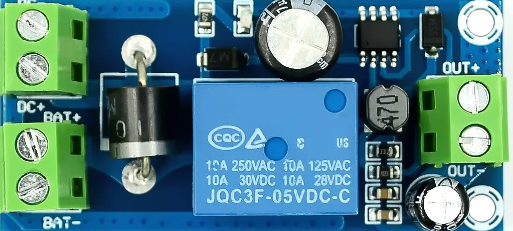
The Commutateur de Tension (Voltage Switch) is a versatile electronic component designed to control the flow of electrical voltage in a circuit. It allows users to select between different voltage levels or toggle the voltage on or off, making it an essential tool in power management and circuit design.
Manufactured by UPS, this component is widely used in applications requiring precise voltage control, such as power supplies, battery management systems, and electronic testing setups. Its robust design ensures reliable operation in both hobbyist and industrial environments.
Explore Projects Built with commutateur de tension


Explore Projects Built with commutateur de tension
Common Applications
- Power supply voltage selection
- Battery charging and management systems
- Voltage regulation in electronic circuits
- Testing and prototyping of multi-voltage systems
- Switching between high and low voltage modes in devices
Technical Specifications
Key Technical Details
| Parameter | Value |
|---|---|
| Manufacturer | UPS |
| Part ID | UPS |
| Operating Voltage Range | 3V to 30V |
| Maximum Current Rating | 5A |
| Switching Type | Manual or Automatic |
| Contact Resistance | ≤ 50 mΩ |
| Insulation Resistance | ≥ 100 MΩ |
| Operating Temperature | -20°C to +85°C |
| Dimensions | 25mm x 15mm x 10mm |
Pin Configuration and Descriptions
The Commutateur de Tension typically has three pins for operation. Below is the pinout description:
| Pin Number | Name | Description |
|---|---|---|
| 1 | Input (V_in) | Connects to the input voltage source. |
| 2 | Output (V_out) | Provides the selected output voltage. |
| 3 | Ground (GND) | Common ground connection for the circuit. |
Usage Instructions
How to Use the Component in a Circuit
- Connect the Input Voltage: Attach the voltage source to the
Input (V_in)pin. Ensure the voltage is within the operating range (3V to 30V). - Connect the Output Load: Connect the device or circuit requiring voltage to the
Output (V_out)pin. - Ground Connection: Connect the
Ground (GND)pin to the common ground of the circuit. - Switch Operation: Use the manual toggle or automatic control (if applicable) to select the desired voltage level or turn the voltage on/off.
Important Considerations
- Voltage Range: Ensure the input voltage does not exceed the maximum rating of 30V to avoid damage.
- Current Rating: Do not exceed the maximum current rating of 5A to prevent overheating or failure.
- Contact Resistance: Periodically check for wear or corrosion on the contacts to maintain low resistance.
- Heat Dissipation: If operating at high currents, ensure adequate ventilation or heat sinking to prevent overheating.
Example: Using with an Arduino UNO
The Commutateur de Tension can be used to control voltage supplied to an Arduino UNO or other microcontroller. Below is an example of how to integrate it into a circuit:
Circuit Setup
- Connect a 12V power supply to the
Input (V_in)pin of the voltage switch. - Connect the
Output (V_out)pin to the VIN pin of the Arduino UNO. - Connect the
Ground (GND)pin to the Arduino's GND pin.
Arduino Code Example
// Example code to monitor voltage levels using Arduino UNO
// Ensure the voltage switch is set to the desired output level

const int voltagePin = A0; // Analog pin to read voltage
float voltage = 0.0;

void setup() {
  Serial.begin(9600); // Initialize serial communication
  pinMode(voltagePin, INPUT); // Set the voltage pin as input
}

void loop() {
  int sensorValue = analogRead(voltagePin); // Read the analog value
  voltage = sensorValue * (5.0 / 1023.0); // Convert to voltage (assuming 5V ref)

  // Print the voltage to the Serial Monitor
  Serial.print("Voltage: ");
  Serial.print(voltage);
  Serial.println(" V");

  delay(1000); // Wait for 1 second before next reading
}
Troubleshooting and FAQs
Common Issues
No Output Voltage:
- Cause: Incorrect wiring or loose connections.
- Solution: Verify all connections, especially the
Input (V_in)andGround (GND)pins.
Overheating:
- Cause: Exceeding the maximum current rating of 5A.
- Solution: Reduce the load current or use a heat sink for better dissipation.
Voltage Drop:
- Cause: High contact resistance due to wear or corrosion.
- Solution: Clean the contacts or replace the switch if necessary.
Intermittent Operation:
- Cause: Faulty switch mechanism or poor soldering.
- Solution: Inspect the switch mechanism and re-solder connections if needed.
FAQs
Q1: Can the voltage switch handle AC voltage?
A1: No, this component is designed for DC voltage only. Using it with AC voltage may damage the switch.
Q2: Can I use this switch for voltages below 3V?
A2: The switch may not operate reliably below 3V. Ensure the input voltage is within the specified range (3V to 30V).
Q3: Is the switch waterproof?
A3: No, the switch is not waterproof. Use it in a dry environment or enclose it in a protective casing if necessary.
Q4: Can I use this switch to toggle between two different voltage sources?
A4: Yes, but ensure the sources share a common ground and do not exceed the voltage and current ratings.
This documentation provides all the necessary details to effectively use and troubleshoot the Commutateur de Tension. For further assistance, refer to the manufacturer's datasheet or contact UPS support.