How to Use ULN2003A Stepper Motor Driver: Examples, Pinouts, and Specs
Introduction
The ULN2003A is a high-voltage, high-current Darlington transistor array designed to drive inductive loads such as stepper motors, relays, and solenoids. It features seven open-collector outputs that can handle up to 500mA per channel and can operate at voltages up to 50V. This makes it an ideal interface between low-power microcontrollers and high-power devices. The ULN2003A is widely used in stepper motor control applications due to its ability to handle high currents and its built-in flyback diodes for inductive load protection.
Explore Projects Built with ULN2003A Stepper Motor Driver

Explore Projects Built with ULN2003A Stepper Motor Driver
Common Applications and Use Cases
- Driving stepper motors in robotics and automation systems
- Controlling relays in home automation and industrial systems
- Operating solenoids in locking mechanisms and valves
- Interfacing microcontrollers with high-power loads
Technical Specifications
Key Technical Details
- Supply Voltage (VCE): Up to 50V
- Output Current (per channel): Up to 500mA
- Number of Channels: 7
- Input Voltage (VIH): 2.7V to 5V (logic high)
- Output Type: Open-collector
- Integrated Flyback Diodes: Yes (for inductive load protection)
- Package Type: DIP-16, SOIC-16
- Operating Temperature Range: -20°C to 85°C
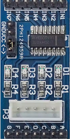
Pin Configuration and Descriptions
The ULN2003A has 16 pins, as described in the table below:
| Pin Number | Name | Description |
|---|---|---|
| 1-7 | IN1-IN7 | Input pins for channels 1 to 7. Connect to the control signals from a microcontroller. |
| 8 | GND | Ground pin. Connect to the ground of the power supply. |
| 9-15 | OUT1-OUT7 | Output pins for channels 1 to 7. Connect to the load (e.g., stepper motor coils). |
| 16 | COM | Common pin for the flyback diodes. Connect to the positive terminal of the load's power supply. |
Usage Instructions
How to Use the ULN2003A in a Circuit
Power Connections:
- Connect the GND pin (Pin 8) to the ground of your power supply.
- Connect the COM pin (Pin 16) to the positive terminal of the load's power supply.
Input Connections:
- Connect the IN1-IN7 pins to the control signals from your microcontroller or logic circuit. These signals should be in the range of 2.7V to 5V for proper operation.
Output Connections:
- Connect the OUT1-OUT7 pins to the load terminals (e.g., stepper motor coils, relay inputs, or solenoids).
Load Protection:
- The ULN2003A includes built-in flyback diodes to protect against voltage spikes generated by inductive loads. Ensure the COM pin is properly connected to the load's power supply to utilize this feature.
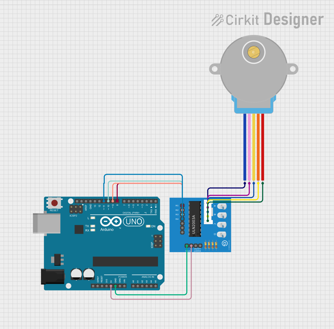
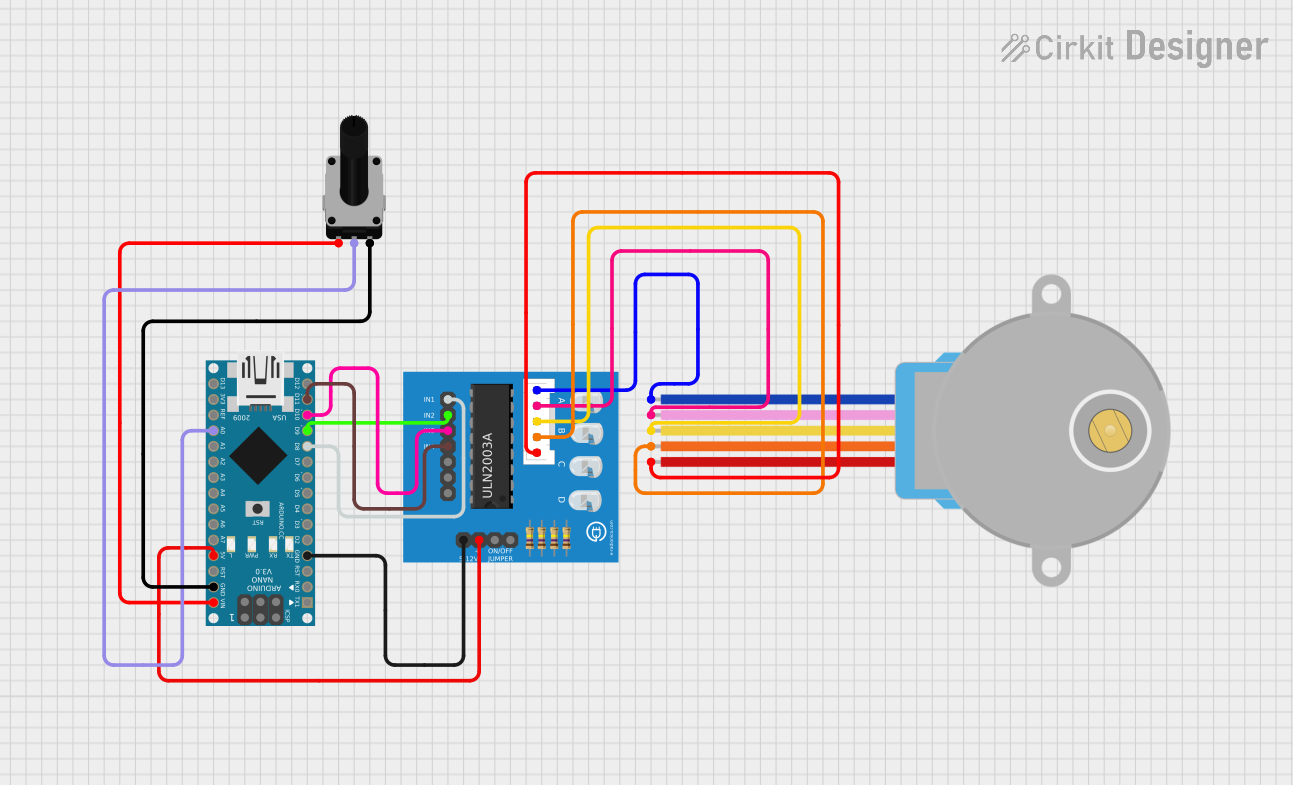
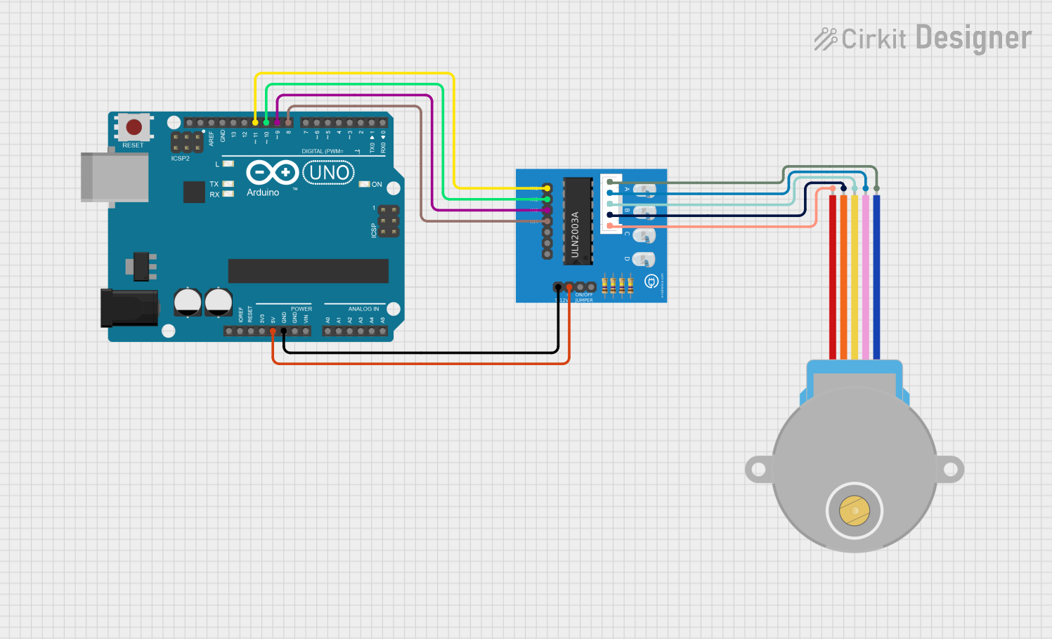
Example: Driving a Stepper Motor with Arduino UNO
Below is an example of how to use the ULN2003A to drive a 28BYJ-48 stepper motor with an Arduino UNO.
Circuit Connections
- Connect the IN1-IN4 pins of the ULN2003A to Arduino digital pins 8, 9, 10, and 11, respectively.
- Connect the OUT1-OUT4 pins to the stepper motor's coil inputs.
- Connect the COM pin to the stepper motor's power supply (e.g., 5V).
- Connect the GND pin to the Arduino's ground.
Arduino Code
// Define the control pins for the ULN2003A
#define IN1 8  // Connect to ULN2003A IN1
#define IN2 9  // Connect to ULN2003A IN2
#define IN3 10 // Connect to ULN2003A IN3
#define IN4 11 // Connect to ULN2003A IN4

// Stepper motor sequence for 28BYJ-48
int stepSequence[4][4] = {
  {1, 0, 0, 1}, // Step 1
  {1, 0, 0, 0}, // Step 2
  {1, 1, 0, 0}, // Step 3
  {0, 1, 0, 0}  // Step 4
};

void setup() {
  // Set control pins as outputs
  pinMode(IN1, OUTPUT);
  pinMode(IN2, OUTPUT);
  pinMode(IN3, OUTPUT);
  pinMode(IN4, OUTPUT);
}

void loop() {
  // Rotate the stepper motor forward
  for (int step = 0; step < 4; step++) {
    for (int pin = 0; pin < 4; pin++) {
      digitalWrite(IN1 + pin, stepSequence[step][pin]);
    }
    delay(10); // Adjust delay for speed control
  }
}
Important Considerations and Best Practices
- Ensure the total current drawn by all channels does not exceed the package's maximum power dissipation.
- Use a proper heat sink or cooling mechanism if the ULN2003A operates near its maximum current rating.
- Verify that the input voltage levels from the microcontroller are compatible with the ULN2003A's input requirements.
- Always connect the COM pin to the load's power supply to enable flyback diode protection.
Troubleshooting and FAQs
Common Issues and Solutions
Problem: The load is not operating as expected.
- Solution: Check the input signals to ensure they are within the required voltage range (2.7V to 5V).
- Solution: Verify that the COM pin is connected to the load's power supply.
Problem: The ULN2003A overheats during operation.
- Solution: Ensure the total current does not exceed the maximum rating of 500mA per channel.
- Solution: Use a heat sink or reduce the load current.
Problem: The stepper motor vibrates but does not rotate.
- Solution: Verify the step sequence in the code and ensure the connections to the motor coils are correct.
- Solution: Check the power supply voltage and current to ensure it meets the motor's requirements.
FAQs
Q: Can I use the ULN2003A with a 3.3V microcontroller?
- A: Yes, the ULN2003A can accept input voltages as low as 2.7V, making it compatible with 3.3V logic.
Q: Do I need external diodes for inductive load protection?
- A: No, the ULN2003A includes built-in flyback diodes for this purpose.
Q: Can I use all seven channels simultaneously?
- A: Yes, but ensure the total current does not exceed the package's maximum power dissipation.
This concludes the documentation for the ULN2003A Stepper Motor Driver.