How to Use DWM1000: Examples, Pinouts, and Specs
Introduction
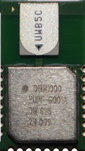
The DWM1000 is a low-power, high-precision Ultra Wideband (UWB) transceiver module manufactured by Decawave. It is designed for real-time location systems (RTLS) and wireless communication, offering accurate distance measurement and positioning capabilities. With a range of up to 200 meters and a precision of up to 10 cm, the DWM1000 is ideal for applications such as indoor navigation, asset tracking, and IoT devices.
Explore Projects Built with DWM1000


Explore Projects Built with DWM1000
Common Applications
- Indoor navigation systems
- Asset and personnel tracking
- Industrial automation
- Internet of Things (IoT) devices
- Robotics and drone positioning
- Wireless sensor networks
Technical Specifications
The DWM1000 module is based on Decawave's DW1000 chip and supports IEEE 802.15.4-2011 UWB standards. Below are the key technical details:
Key Specifications
| Parameter | Value |
|---|---|
| Operating Voltage | 2.8V to 3.6V |
| Current Consumption | 35 mA (active mode), 1 µA (sleep) |
| Frequency Range | 3.5 GHz to 6.5 GHz |
| Communication Protocol | IEEE 802.15.4-2011 UWB |
| Data Rate | 110 kbps, 850 kbps, 6.8 Mbps |
| Range | Up to 200 meters |
| Positioning Accuracy | ±10 cm |
| Operating Temperature | -40°C to +85°C |
| Dimensions | 23 mm x 13 mm x 2.2 mm |
Pin Configuration
The DWM1000 module has 24 pins, which are used for power, communication, and control. Below is the pinout description:
| Pin Number | Name | Description |
|---|---|---|
| 1 | GND | Ground |
| 2 | VDD | Power supply (2.8V to 3.6V) |
| 3 | SPI_MOSI | SPI Master Out Slave In |
| 4 | SPI_MISO | SPI Master In Slave Out |
| 5 | SPI_CLK | SPI Clock |
| 6 | SPI_CS | SPI Chip Select (active low) |
| 7 | IRQ | Interrupt Request Output |
| 8 | RSTn | Reset (active low) |
| 9 | WAKE_UP | Wake-up pin for sleep mode |
| 10 | GPIO1 | General Purpose I/O |
| 11 | GPIO2 | General Purpose I/O |
| 12 | GPIO3 | General Purpose I/O |
| 13 | GPIO4 | General Purpose I/O |
| 14 | GPIO5 | General Purpose I/O |
| 15 | GPIO6 | General Purpose I/O |
| 16 | GPIO7 | General Purpose I/O |
| 17 | GPIO8 | General Purpose I/O |
| 18 | GPIO9 | General Purpose I/O |
| 19 | GPIO10 | General Purpose I/O |
| 20 | GPIO11 | General Purpose I/O |
| 21 | GPIO12 | General Purpose I/O |
| 22 | GPIO13 | General Purpose I/O |
| 23 | GPIO14 | General Purpose I/O |
| 24 | GPIO15 | General Purpose I/O |
Usage Instructions
The DWM1000 module can be integrated into a circuit using its SPI interface for communication. Below are the steps to use the module effectively:
Connecting the DWM1000 to an Arduino UNO
- Power Supply: Connect the
VDDpin to the 3.3V output of the Arduino and theGNDpin to the Arduino's ground. - SPI Interface: Connect the SPI pins of the DWM1000 to the corresponding SPI pins on the Arduino:
SPI_MOSI→ Arduino pin 11SPI_MISO→ Arduino pin 12SPI_CLK→ Arduino pin 13SPI_CS→ Arduino pin 10
- Interrupt Pin: Connect the
IRQpin to an available digital pin on the Arduino (e.g., pin 2). - Reset Pin: Connect the
RSTnpin to another digital pin on the Arduino (e.g., pin 3).
Sample Arduino Code
Below is an example of how to initialize and communicate with the DWM1000 module using an Arduino UNO:
#include <SPI.h>

// Pin definitions
#define DWM1000_CS 10  // Chip Select pin
#define DWM1000_RST 3  // Reset pin
#define DWM1000_IRQ 2  // Interrupt pin

void setup() {
  // Initialize Serial Monitor
  Serial.begin(9600);
  while (!Serial);

  // Initialize SPI
  SPI.begin();
  pinMode(DWM1000_CS, OUTPUT);
  pinMode(DWM1000_RST, OUTPUT);
  pinMode(DWM1000_IRQ, INPUT);

  // Reset the DWM1000 module
  digitalWrite(DWM1000_RST, LOW);
  delay(10);
  digitalWrite(DWM1000_RST, HIGH);
  delay(10);

  Serial.println("DWM1000 Initialized");
}

void loop() {
  // Example: Send a command to the DWM1000
  digitalWrite(DWM1000_CS, LOW);  // Select the DWM1000
  SPI.transfer(0x01);            // Example command
  digitalWrite(DWM1000_CS, HIGH); // Deselect the DWM1000

  delay(1000); // Wait for 1 second
}
Best Practices
- Ensure the power supply voltage is within the specified range (2.8V to 3.6V).
- Use proper decoupling capacitors near the power pins to reduce noise.
- Keep SPI connections as short as possible to minimize signal degradation.
- Use a level shifter if interfacing with a 5V microcontroller, as the DWM1000 operates at 3.3V logic levels.
Troubleshooting and FAQs
Common Issues
No Communication with the Module
- Cause: Incorrect SPI connections or configuration.
- Solution: Verify the SPI wiring and ensure the correct SPI settings (mode, clock speed) are used.
Module Not Responding
- Cause: The module is not properly powered or reset.
- Solution: Check the power supply voltage and ensure the
RSTnpin is toggled during initialization.
Inaccurate Distance Measurements
- Cause: Environmental interference or incorrect calibration.
- Solution: Ensure a clear line of sight between modules and perform proper calibration.
High Power Consumption
- Cause: The module is not entering sleep mode.
- Solution: Use the
WAKE_UPpin to manage sleep mode and reduce power consumption.
FAQs
Q: Can the DWM1000 be used outdoors?
A: Yes, but the range and accuracy may be affected by environmental factors such as obstacles and interference.
Q: What is the maximum data rate supported by the DWM1000?
A: The DWM1000 supports data rates of up to 6.8 Mbps.
Q: Is the DWM1000 compatible with other UWB devices?
A: Yes, it complies with the IEEE 802.15.4-2011 UWB standard, ensuring compatibility with other compliant devices.
Q: How can I increase the range of the DWM1000?
A: Use external antennas and ensure a clear line of sight between devices to maximize range.
Q: Does the DWM1000 support multi-node communication?
A: Yes, the module can be used in multi-node RTLS systems for tracking multiple devices simultaneously.