
How to Use PIC32MX440F512H: Examples, Pinouts, and Specs

 Design with PIC32MX440F512H in Cirkit Designer
Introduction
The PIC32MX440F512H is a 32-bit microcontroller from Microchip's PIC32 family, designed for high-performance embedded applications. It is based on the MIPS M4K core architecture and offers a robust set of features, including 512 KB of Flash memory, 128 KB of SRAM, and a wide range of peripherals. This microcontroller is ideal for applications requiring advanced processing power, such as industrial automation, IoT devices, motor control, and multimedia systems.
Explore Projects Built with PIC32MX440F512H
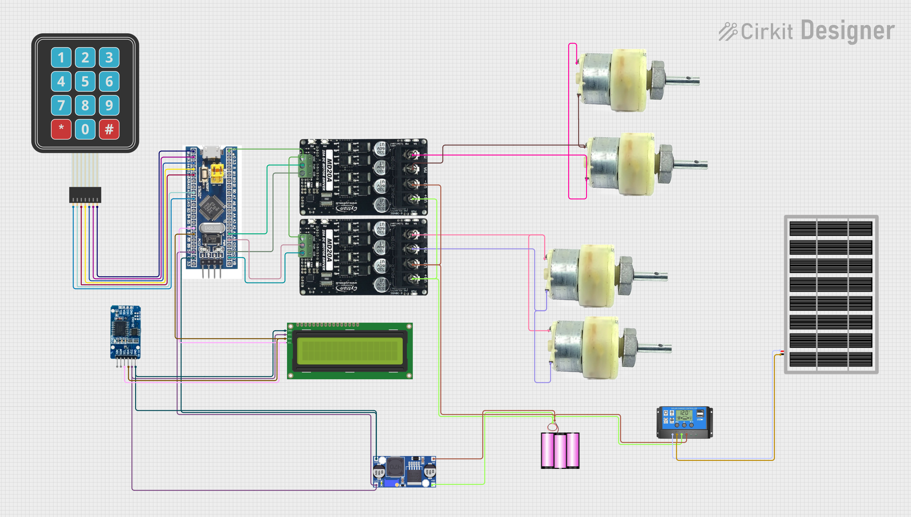 Open Project in Cirkit Designer
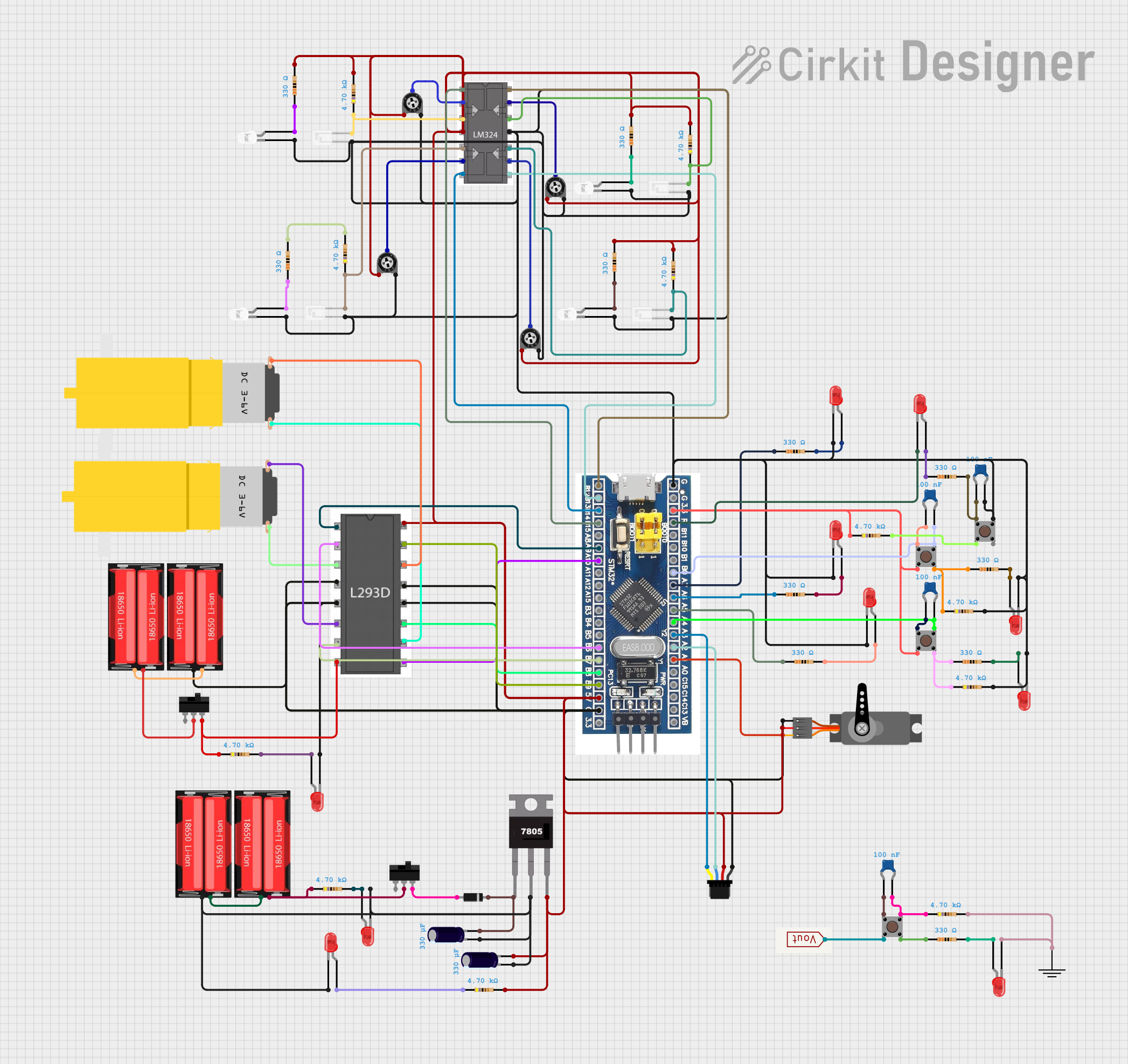 Open Project in Cirkit Designer
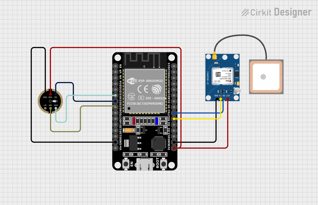 Open Project in Cirkit Designer
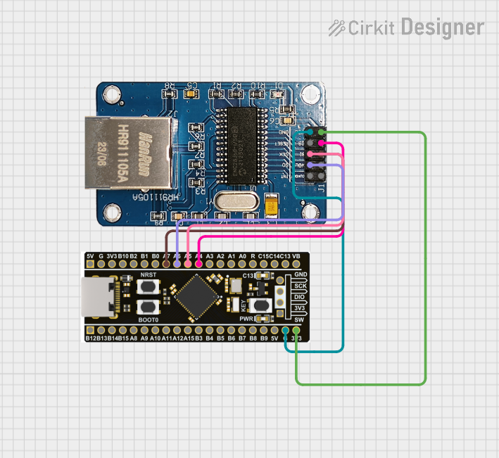 Open Project in Cirkit Designer
Explore Projects Built with PIC32MX440F512H
Open Project in Cirkit DesignerOpen Project in Cirkit DesignerOpen Project in Cirkit DesignerOpen Project in Cirkit DesignerCommon Applications
- Industrial control systems
- IoT devices and smart home applications
- Motor control and robotics
- Multimedia and audio processing
- Data acquisition and signal processing
Technical Specifications
Key Features
- Core Architecture: MIPS32 M4K
- Operating Voltage: 2.3V to 3.6V
- Flash Memory: 512 KB
- SRAM: 128 KB
- Clock Speed: Up to 80 MHz
- I/O Pins: Up to 85
- Communication Interfaces: UART, SPI, I2C, CAN
- Timers: 5 x 16-bit timers, 1 x 32-bit timer
- ADC: 10-bit, up to 16 channels
- PWM Outputs: 5
- Package Options: TQFP-64, QFN-64
Pin Configuration
The PIC32MX440F512H is available in a 64-pin package. Below is a summary of the pin configuration:
| Pin Number | Pin Name | Function | Description |
|---|---|---|---|
| 1 | VDD | Power Supply | Positive power supply (3.3V) |
| 2 | VSS | Ground | Ground connection |
| 3 | OSC1/CLKI | Oscillator Input/Clock Input | External clock or crystal input |
| 4 | OSC2/CLKO | Oscillator Output/Clock Output | External clock or crystal output |
| 5 | MCLR | Master Clear (Reset) | Active-low reset input |
| 6-13 | RA0-RA7 | GPIO/Analog Input | General-purpose I/O or ADC channels |
| 14-21 | RB0-RB7 | GPIO/Peripheral Functions | General-purpose I/O or peripherals |
| 22-64 | Various | GPIO/Peripheral Functions | Configurable for UART, SPI, I2C, etc. |
Refer to the official datasheet for a complete pinout and detailed descriptions.
Usage Instructions
Using the PIC32MX440F512H in a Circuit
- Power Supply: Connect the VDD pin to a 3.3V power source and the VSS pin to ground.
- Oscillator: Use an external crystal oscillator (e.g., 8 MHz) connected to the OSC1 and OSC2 pins, or configure an internal oscillator.
- Reset: Connect the MCLR pin to a pull-up resistor (e.g., 10 kΩ) to VDD for proper reset functionality.
- Programming: Use an ICSP (In-Circuit Serial Programming) tool, such as Microchip's PICkit, to program the microcontroller.
- Peripherals: Configure the GPIO pins and peripherals (UART, SPI, I2C, etc.) in the firmware as needed for your application.
Example: Interfacing with an Arduino UNO
Although the PIC32MX440F512H is a standalone microcontroller, it can communicate with an Arduino UNO via UART. Below is an example of Arduino code to send data to the PIC32MX440F512H:
// Arduino UNO UART Communication Example
// Sends "Hello, PIC32!" to the PIC32MX440F512H via UART

void setup() {
  Serial.begin(9600); // Initialize UART at 9600 baud rate
}

void loop() {
  Serial.println("Hello, PIC32!"); // Send data to PIC32
  delay(1000); // Wait for 1 second before sending again
}
On the PIC32MX440F512H side, configure the UART module to receive the data. Below is an example of PIC32 code using MPLAB X IDE and XC32 compiler:
// PIC32MX440F512H UART Receive Example
// Receives data from Arduino UNO and echoes it back

#include <xc.h>

#define SYSCLK 80000000 // System clock frequency (80 MHz)
#define PBCLK 40000000  // Peripheral bus clock frequency (40 MHz)

void UART1_Init() {
    U1MODE = 0x8000; // Enable UART1, 8-bit data, no parity
    U1BRG = (PBCLK / (16 * 9600)) - 1; // Set baud rate to 9600
    U1STA = 0x0400; // Enable UART1 transmit
}

char UART1_Read() {
    while (!U1STAbits.URXDA); // Wait until data is available
    return U1RXREG; // Return received character
}

void UART1_Write(char data) {
    while (U1STAbits.UTXBF); // Wait until transmit buffer is empty
    U1TXREG = data; // Transmit character
}

int main() {
    UART1_Init(); // Initialize UART1

    while (1) {
        char received = UART1_Read(); // Read data from UART
        UART1_Write(received); // Echo received data back
    }

    return 0;
}
Best Practices
- Use decoupling capacitors (e.g., 0.1 µF) near the VDD pins to reduce noise.
- Avoid leaving unused pins floating; configure them as outputs or connect to ground.
- Use proper ESD protection when handling the microcontroller.
Troubleshooting and FAQs
Common Issues
Microcontroller Not Responding
- Ensure the power supply voltage is within the specified range (2.3V to 3.6V).
- Verify the MCLR pin is properly connected with a pull-up resistor.
- Check the oscillator configuration and ensure the crystal is functioning.
UART Communication Fails
- Confirm the baud rate settings match between the PIC32 and the external device.
- Check the TX and RX pin connections for proper wiring.
Programming Errors
- Ensure the ICSP connections are correct and the programmer is functioning.
- Verify the microcontroller is not in a low-power or sleep mode during programming.
FAQs
Q: Can I use the internal oscillator instead of an external crystal?
A: Yes, the PIC32MX440F512H has an internal oscillator that can be used, but an external crystal provides better accuracy for timing-critical applications.
Q: How do I increase the clock speed to 80 MHz?
A: Configure the PLL (Phase-Locked Loop) settings in the firmware to achieve the desired clock speed. Refer to the datasheet for detailed instructions.
Q: What is the maximum current draw for the I/O pins?
A: Each I/O pin can source or sink up to 18 mA, with a total maximum current of 200 mA for all pins combined.
By following this documentation, you can effectively integrate the PIC32MX440F512H into your embedded projects. For more details, consult the official datasheet and reference manual.