Cirkit Designer Logo
Cirkit Designer
Your all-in-one circuit design IDE
Home / 
Component Documentation

How to Use FLE-113-01-G-DV-K: Examples, Pinouts, and Specs

Image of FLE-113-01-G-DV-K
Cirkit Designer LogoDesign with FLE-113-01-G-DV-K in Cirkit Designer

Introduction

The FLE-113-01-G-DV-K is a compact LED indicator light designed for panel mounting. It is widely used in electronic circuits to provide visual feedback or status indication. This component is known for its low power consumption, durability, and availability in multiple colors, making it suitable for a variety of applications.

Explore Projects Built with FLE-113-01-G-DV-K

Use Cirkit Designer to design, explore, and prototype these projects online. Some projects support real-time simulation. Click "Open Project" to start designing instantly!
Cellular-Enabled IoT Device with Real-Time Clock and Power Management
Image of LRCM PHASE 2 BASIC: A project utilizing FLE-113-01-G-DV-K in a practical application
This circuit features a LilyGo-SIM7000G module for cellular communication and GPS functionality, interfaced with an RTC DS3231 for real-time clock capabilities. It includes voltage sensing through two voltage sensor modules, and uses an 8-channel opto-coupler for isolating different parts of the circuit. Power management is handled by a buck converter connected to a DC power source and batteries, with a fuse for protection and a rocker switch for on/off control. Additionally, there's an LED for indication purposes.
Cirkit Designer LogoOpen Project in Cirkit Designer
ESP32-Based Security System with RFID and Laser Intrusion Detection
Image of CPE doorlock system upgrade: A project utilizing FLE-113-01-G-DV-K in a practical application
This circuit is a security and access control system featuring motion detection, laser beam-break sensing, and RFID scanning, interfaced with a keypad and visual/audible indicators, powered by a solar-charged battery, and capable of controlling an electric lock via a relay.
Cirkit Designer LogoOpen Project in Cirkit Designer
ESP32-Based Security System with RFID and Laser Tripwire
Image of CPE doorlock system: A project utilizing FLE-113-01-G-DV-K in a practical application
This circuit is designed for a comprehensive security and access control system with motion detection, access via RFID, and a break-beam sensor. It includes a solenoid lock controlled by a relay, visual and audible alerts, and a robust power management system with solar and battery backup to ensure uninterrupted operation.
Cirkit Designer LogoOpen Project in Cirkit Designer
Solar-Powered Environmental Monitoring Station with GSM Reporting
Image of thesis nila po: A project utilizing FLE-113-01-G-DV-K in a practical application
This is a solar-powered monitoring and control system with automatic power source selection, environmental sensing, and communication capabilities. It uses an ESP32 microcontroller to process inputs from gas, flame, and temperature sensors, and to manage outputs like an LCD display, LEDs, and a buzzer. The system can communicate via a SIM900A module and switch between solar and AC power sources using an ATS.
Cirkit Designer LogoOpen Project in Cirkit Designer

Explore Projects Built with FLE-113-01-G-DV-K

Use Cirkit Designer to design, explore, and prototype these projects online. Some projects support real-time simulation. Click "Open Project" to start designing instantly!
Image of LRCM PHASE 2 BASIC: A project utilizing FLE-113-01-G-DV-K in a practical application
Cellular-Enabled IoT Device with Real-Time Clock and Power Management
This circuit features a LilyGo-SIM7000G module for cellular communication and GPS functionality, interfaced with an RTC DS3231 for real-time clock capabilities. It includes voltage sensing through two voltage sensor modules, and uses an 8-channel opto-coupler for isolating different parts of the circuit. Power management is handled by a buck converter connected to a DC power source and batteries, with a fuse for protection and a rocker switch for on/off control. Additionally, there's an LED for indication purposes.
Cirkit Designer LogoOpen Project in Cirkit Designer
Image of CPE doorlock system upgrade: A project utilizing FLE-113-01-G-DV-K in a practical application
ESP32-Based Security System with RFID and Laser Intrusion Detection
This circuit is a security and access control system featuring motion detection, laser beam-break sensing, and RFID scanning, interfaced with a keypad and visual/audible indicators, powered by a solar-charged battery, and capable of controlling an electric lock via a relay.
Cirkit Designer LogoOpen Project in Cirkit Designer
Image of CPE doorlock system: A project utilizing FLE-113-01-G-DV-K in a practical application
ESP32-Based Security System with RFID and Laser Tripwire
This circuit is designed for a comprehensive security and access control system with motion detection, access via RFID, and a break-beam sensor. It includes a solenoid lock controlled by a relay, visual and audible alerts, and a robust power management system with solar and battery backup to ensure uninterrupted operation.
Cirkit Designer LogoOpen Project in Cirkit Designer
Image of thesis nila po: A project utilizing FLE-113-01-G-DV-K in a practical application
Solar-Powered Environmental Monitoring Station with GSM Reporting
This is a solar-powered monitoring and control system with automatic power source selection, environmental sensing, and communication capabilities. It uses an ESP32 microcontroller to process inputs from gas, flame, and temperature sensors, and to manage outputs like an LCD display, LEDs, and a buzzer. The system can communicate via a SIM900A module and switch between solar and AC power sources using an ATS.
Cirkit Designer LogoOpen Project in Cirkit Designer

Common Applications and Use Cases

  • Status indication in control panels
  • Power-on indicators in electronic devices
  • Fault or error signaling in industrial equipment
  • User feedback in consumer electronics
  • Automotive dashboard indicators

Technical Specifications

Below are the key technical details of the FLE-113-01-G-DV-K:

Parameter Value
Operating Voltage 2.0V to 3.3V (typical 2.2V)
Forward Current (If) 20mA (typical)
Power Consumption < 0.1W
Mounting Type Panel Mount
LED Colors Available Red, Green, Yellow, Blue
Viewing Angle 120°
Housing Material Polycarbonate (PC)
Operating Temperature -40°C to +85°C
Dimensions 11.3mm x 5.0mm x 5.0mm

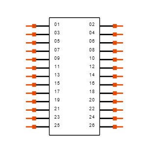
Pin Configuration and Descriptions

The FLE-113-01-G-DV-K has two pins for electrical connection. The table below describes the pin configuration:

Pin Number Name Description
1 Anode (+) Connect to the positive terminal of the power supply.
2 Cathode (-) Connect to the negative terminal or ground.

Usage Instructions

How to Use the FLE-113-01-G-DV-K in a Circuit

  1. Determine the Operating Voltage: Ensure the power supply voltage matches the LED's operating voltage (2.0V to 3.3V). Use a current-limiting resistor to prevent overcurrent.

  2. Calculate the Resistor Value: Use Ohm's Law to calculate the resistor value: [ R = \frac{V_{supply} - V_{forward}}{I_{forward}} ] For example, if the supply voltage is 5V and the forward voltage is 2.2V with a forward current of 20mA: [ R = \frac{5V - 2.2V}{0.02A} = 140\ \Omega ] Use the nearest standard resistor value (e.g., 150Ω).

  3. Connect the LED:

    • Connect the anode (longer pin) to the positive terminal of the power supply through the resistor.
    • Connect the cathode (shorter pin) to the ground.
  4. Test the Circuit: Power on the circuit and verify that the LED lights up.

Important Considerations and Best Practices

  • Polarity: Ensure correct polarity when connecting the LED. Reversing the polarity may damage the component.
  • Current Limiting: Always use a resistor to limit the current through the LED.
  • Heat Management: Operate the LED within the specified temperature range to avoid overheating.
  • Panel Mounting: Secure the LED properly in the panel to prevent mechanical stress.

Example: Connecting to an Arduino UNO

The FLE-113-01-G-DV-K can be easily connected to an Arduino UNO for status indication. Below is an example code to blink the LED:

// Define the pin connected to the LED
const int ledPin = 13; // Use digital pin 13 for the LED

void setup() {
  pinMode(ledPin, OUTPUT); // Set the LED pin as an output
}

void loop() {
  digitalWrite(ledPin, HIGH); // Turn the LED on
  delay(1000); // Wait for 1 second
  digitalWrite(ledPin, LOW); // Turn the LED off
  delay(1000); // Wait for 1 second
}

Troubleshooting and FAQs

Common Issues and Solutions

  1. LED Does Not Light Up:

    • Cause: Incorrect polarity.

    • Solution: Verify the anode and cathode connections.

    • Cause: No current-limiting resistor.

    • Solution: Add a resistor in series with the LED.

  2. LED Flickers:

    • Cause: Unstable power supply.
    • Solution: Use a regulated power supply or add a capacitor for filtering.
  3. LED Burns Out:

    • Cause: Excessive current.
    • Solution: Recalculate the resistor value and ensure it limits the current to 20mA.
  4. LED is Dim:

    • Cause: Insufficient voltage or high resistor value.
    • Solution: Verify the supply voltage and adjust the resistor value.

FAQs

Q1: Can I use the FLE-113-01-G-DV-K with a 12V power supply?
A1: Yes, but you must use an appropriate resistor to limit the current. For a 12V supply, calculate the resistor value as follows: [ R = \frac{12V - 2.2V}{0.02A} = 490\ \Omega ] Use a 470Ω or 510Ω resistor.

Q2: Is the LED waterproof?
A2: No, the FLE-113-01-G-DV-K is not waterproof. Use it in dry environments or enclosures.

Q3: Can I use PWM to dim the LED?
A3: Yes, the LED can be dimmed using Pulse Width Modulation (PWM) from a microcontroller like Arduino.

Q4: What is the lifespan of the LED?
A4: The typical lifespan is 50,000 hours under normal operating conditions.

This concludes the documentation for the FLE-113-01-G-DV-K.