How to Use curiosity nano: Examples, Pinouts, and Specs
Introduction
The Curiosity Nano is a compact, low-power microcontroller platform designed for Internet of Things (IoT) applications. It features built-in wireless connectivity and an array of onboard sensors, making it ideal for environmental monitoring, smart home devices, and other connected applications. Its small form factor and energy-efficient design make it a versatile choice for both prototyping and deployment in embedded systems.
Explore Projects Built with curiosity nano
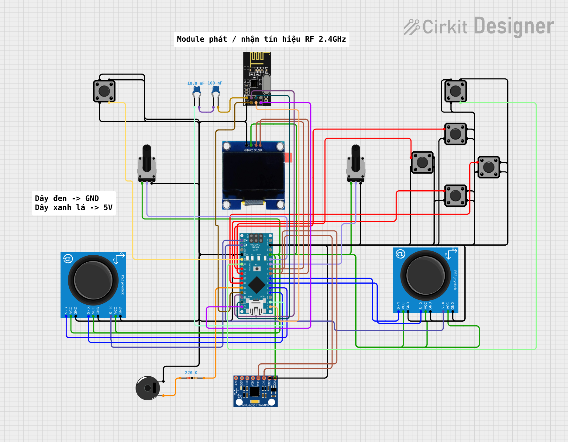
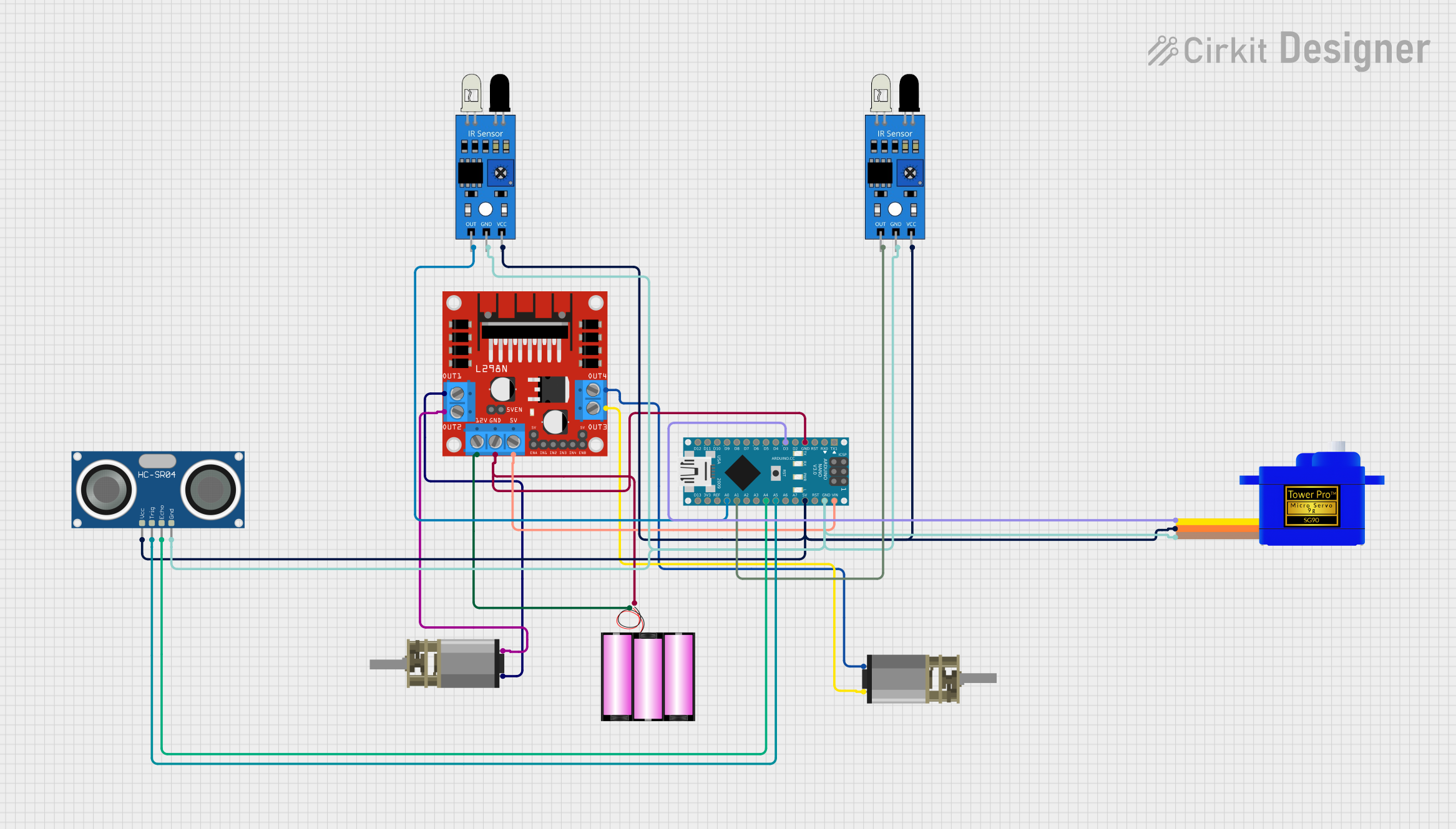
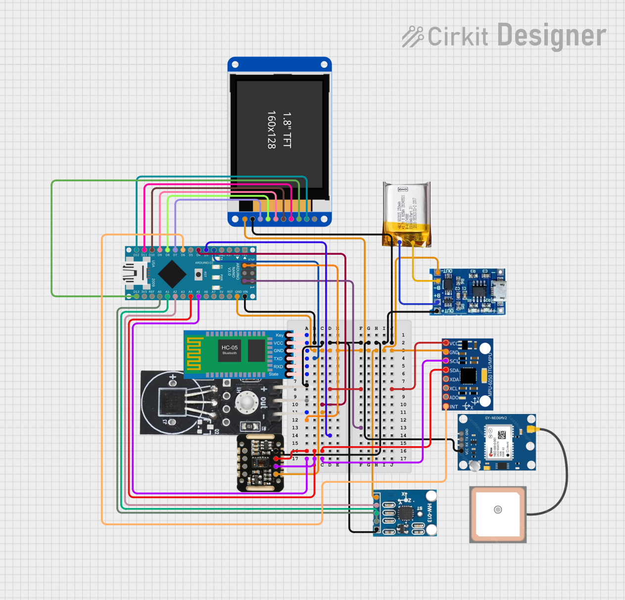
Explore Projects Built with curiosity nano
Common Applications and Use Cases
- IoT devices and smart home automation
- Environmental monitoring (e.g., temperature, humidity, air quality)
- Wearable technology
- Prototyping low-power, wireless-enabled systems
- Educational projects and learning platforms
Technical Specifications
Key Technical Details
| Specification | Value |
|---|---|
| Microcontroller | Varies by model (e.g., ATmega4809, SAMD21) |
| Operating Voltage | 3.3V |
| Input Voltage Range | 3.3V to 5V (via USB or external supply) |
| Wireless Connectivity | Integrated (e.g., Bluetooth, Wi-Fi) |
| Onboard Sensors | Temperature, humidity, light, etc. |
| Clock Speed | Up to 48 MHz |
| Flash Memory | Up to 256 KB |
| SRAM | Up to 32 KB |
| GPIO Pins | Varies by model (typically 14-20) |
| Communication Interfaces | UART, SPI, I2C, USB |
| Dimensions | ~20mm x 50mm |
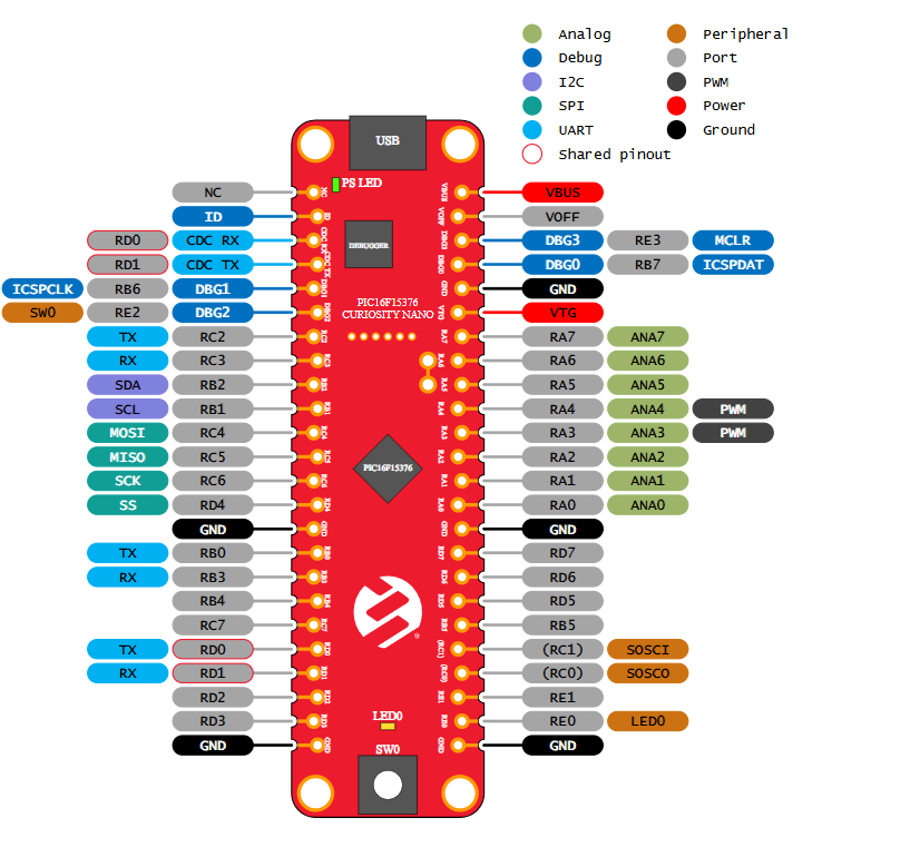
Pin Configuration and Descriptions
| Pin Name | Description |
|---|---|
| VCC | Power supply input (3.3V) |
| GND | Ground connection |
| GPIO | General-purpose input/output pins (digital or analog, depending on model) |
| UART (TX/RX) | Serial communication pins for UART interface |
| SPI (MISO/MOSI) | SPI communication pins (Master In Slave Out, Master Out Slave In) |
| I2C (SCL/SDA) | I2C communication pins (Clock and Data lines) |
| RESET | Reset pin to restart the microcontroller |
| USB | USB interface for programming and power |
Usage Instructions
How to Use the Curiosity Nano in a Circuit
Powering the Board:
- Connect the Curiosity Nano to a computer or USB power source using a micro-USB cable.
- Alternatively, supply 3.3V to the VCC pin and connect GND to the ground of your circuit.
Programming the Microcontroller:
- Use an Integrated Development Environment (IDE) such as MPLAB X or Arduino IDE (if supported).
- Select the appropriate board and microcontroller model in the IDE settings.
- Write your code and upload it to the board via the USB interface.
Connecting Sensors and Actuators:
- Use the GPIO pins to connect external sensors, actuators, or other peripherals.
- Ensure that the voltage and current requirements of connected devices are compatible with the board.
Wireless Connectivity:
- Configure the built-in wireless module (e.g., Wi-Fi or Bluetooth) using the provided libraries or firmware.
- Follow the manufacturer's documentation for specific wireless setup instructions.
Important Considerations and Best Practices
- Voltage Levels: Ensure all connected devices operate at 3.3V logic levels to avoid damage.
- Pin Usage: Refer to the pin configuration table to avoid conflicts between peripherals.
- Heat Management: Avoid prolonged operation at maximum current to prevent overheating.
- Firmware Updates: Regularly check for firmware updates to ensure optimal performance and security.
Example Code for Arduino UNO
If the Curiosity Nano is compatible with Arduino IDE, the following example demonstrates how to read data from an onboard temperature sensor and send it via serial communication:
// Example: Reading temperature from onboard sensor and sending via Serial

#include <Wire.h> // Include Wire library for I2C communication

#define TEMP_SENSOR_ADDR 0x48 // Replace with the actual I2C address of the sensor

void setup() {
  Serial.begin(9600); // Initialize serial communication at 9600 baud
  Wire.begin();       // Initialize I2C communication
  Serial.println("Curiosity Nano Temperature Sensor Example");
}

void loop() {
  Wire.beginTransmission(TEMP_SENSOR_ADDR); // Start communication with sensor
  Wire.write(0x00);                         // Request temperature data (register 0x00)
  Wire.endTransmission();

  Wire.requestFrom(TEMP_SENSOR_ADDR, 2);    // Request 2 bytes of data from sensor
  if (Wire.available() == 2) {              // Check if 2 bytes are available
    int tempRaw = (Wire.read() << 8) | Wire.read(); // Combine MSB and LSB
    float temperature = tempRaw * 0.02 - 273.15;    // Convert to Celsius
    Serial.print("Temperature: ");
    Serial.print(temperature);
    Serial.println(" °C");
  }

  delay(1000); // Wait 1 second before next reading
}
Troubleshooting and FAQs
Common Issues and Solutions
Board Not Detected by IDE:
- Ensure the correct drivers are installed for the Curiosity Nano.
- Verify the USB cable is functional and supports data transfer.
- Check that the correct board and port are selected in the IDE.
Wireless Connectivity Problems:
- Double-check the wireless module configuration and credentials.
- Ensure the board is within range of the wireless network.
- Update the firmware of the wireless module if necessary.
Sensor Readings Are Incorrect:
- Verify the sensor connections and ensure proper I2C/SPI configuration.
- Check for any loose wires or poor soldering.
- Calibrate the sensor if required.
Overheating or Power Issues:
- Ensure the board is not drawing more current than the power source can supply.
- Avoid short circuits by carefully inspecting the wiring.
FAQs
Q: Can I use the Curiosity Nano with a 5V power supply?
A: The Curiosity Nano operates at 3.3V. While it can accept 5V input via USB, ensure all connected peripherals are compatible with 3.3V logic levels.
Q: Is the Curiosity Nano compatible with Arduino libraries?
A: Some models of the Curiosity Nano are compatible with Arduino IDE and libraries. Check the specific microcontroller model for compatibility.
Q: How do I update the firmware?
A: Use the manufacturer's firmware update tool or IDE to flash the latest firmware. Refer to the official documentation for detailed instructions.
Q: Can I use external sensors with the Curiosity Nano?
A: Yes, the GPIO pins support external sensors. Ensure proper voltage levels and communication protocols (e.g., I2C, SPI) are used.