How to Use Mini 560 Step Down 20-7V to 5V: Examples, Pinouts, and Specs
Introduction
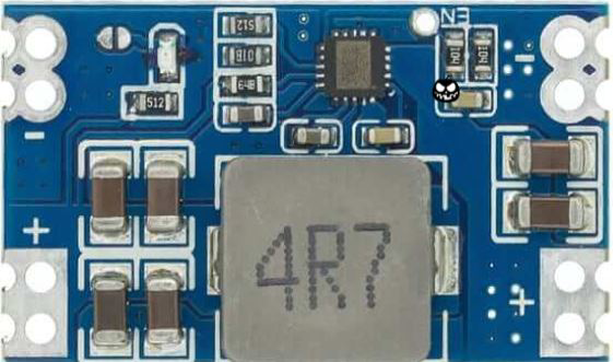
The Mini 560 Step Down Voltage Regulator is a compact, high-efficiency, buck converter designed to convert a higher voltage input (ranging from 20V to 7V) to a stable 5V output. This component is ideal for powering 5V electronics from a higher voltage source, making it a versatile choice for projects that require a regulated 5V supply.
Explore Projects Built with Mini 560 Step Down 20-7V to 5V


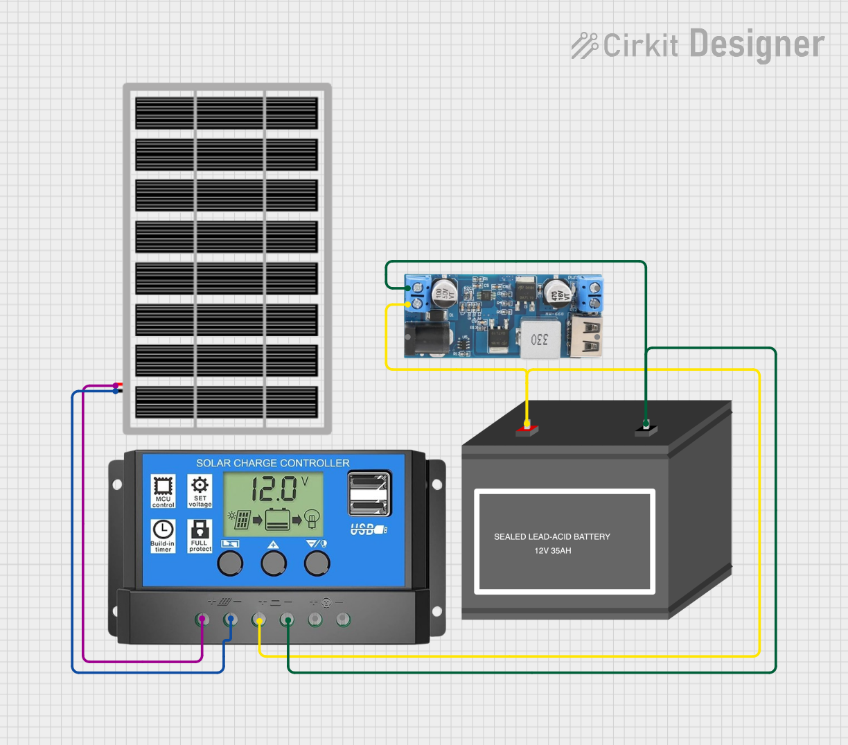
Explore Projects Built with Mini 560 Step Down 20-7V to 5V
Common Applications and Use Cases
- Powering 5V USB devices
- Supplying 5V to microcontrollers like Arduino or Raspberry Pi when a higher voltage power source is available
- Mobile applications where battery voltage can fluctuate
- Robotics and DIY electronics projects
Technical Specifications
Key Technical Details
- Input Voltage: 7V to 20V
- Output Voltage: 5V
- Maximum Output Current: 3A (with proper heat sinking)
- Efficiency: Up to 92%
- Operating Temperature: -40°C to +85°C
Pin Configuration and Descriptions
| Pin Number | Name | Description |
|---|---|---|
| 1 | VIN | Input voltage (7V to 20V) |
| 2 | GND | Ground connection |
| 3 | VOUT | Regulated 5V output |
| 4 | EN | Enable pin (active high) |
Usage Instructions
How to Use the Component in a Circuit
- Connect the input voltage (7V to 20V) to the VIN pin.
- Connect the ground from your power source to the GND pin.
- The VOUT pin will provide the regulated 5V output.
- The EN pin can be left unconnected for normal operation, or connected to a logic high signal to enable the regulator.
Important Considerations and Best Practices
- Ensure that the input voltage does not exceed 20V to prevent damage to the regulator.
- Do not exceed the maximum output current of 3A. For currents above 1A, use proper heat sinking.
- Place a capacitor (typically 10µF or greater) close to the input and output pins to minimize voltage spikes and improve stability.
- Avoid running the regulator at high output currents for extended periods without adequate cooling.
Troubleshooting and FAQs
Common Issues Users Might Face
- Output voltage is lower than 5V: Check if the input voltage is within the specified range and if the output current is not exceeding the maximum rating.
- Regulator is overheating: Ensure that the current draw is within limits and that adequate heat sinking is provided.
Solutions and Tips for Troubleshooting
- If the output voltage is incorrect, verify the input voltage and load conditions.
- If the regulator overheats, reduce the load current, improve ventilation, or add a heat sink to the regulator.
FAQs
Q: Can I use this regulator to power a 5V microcontroller? A: Yes, the Mini 560 Step Down can be used to power any 5V microcontroller as long as the current requirements do not exceed 3A.
Q: What happens if I exceed the maximum input voltage? A: Exceeding the maximum input voltage can damage the regulator. Always ensure the input voltage is within the specified range.
Q: Is it necessary to use capacitors with this regulator? A: While the regulator may work without capacitors, it is recommended to use input and output capacitors for improved stability and to minimize voltage spikes.
Example Code for Arduino UNO
// This example demonstrates how to use the Mini 560 Step Down with an Arduino UNO.

void setup() {
  // Initialize the Serial communication to send data to the computer
  Serial.begin(9600);
  // Configure the EN pin as an output
  pinMode(7, OUTPUT); // Assuming the EN pin is connected to pin 7 on the Arduino
}

void loop() {
  // Enable the Mini 560 Step Down
  digitalWrite(7, HIGH);
  Serial.println("Voltage Regulator Enabled");
  delay(5000); // Wait for 5 seconds

  // Disable the Mini 560 Step Down
  digitalWrite(7, LOW);
  Serial.println("Voltage Regulator Disabled");
  delay(5000); // Wait for 5 seconds
}
Note: The above code assumes that the EN pin of the Mini 560 Step Down is connected to digital pin 7 on the Arduino UNO. The EN pin is used to enable or disable the voltage regulator from the Arduino.