How to Use mkem0004_potentialmeter_module: Examples, Pinouts, and Specs
Introduction
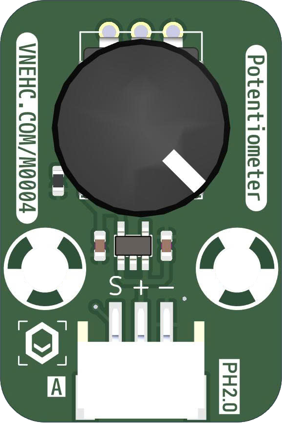
The MKEM0004_Potentiometer_Module is a versatile electronic component manufactured by MKEVN. It is designed to provide variable resistance, enabling users to adjust voltage levels and control current flow in a circuit. This module is ideal for applications requiring fine-tuning of electrical parameters, such as brightness control, audio volume adjustment, and sensor calibration.
Explore Projects Built with mkem0004_potentialmeter_module


Explore Projects Built with mkem0004_potentialmeter_module
Common Applications and Use Cases
- Brightness Control: Adjusting the intensity of LEDs or displays.
- Audio Systems: Controlling volume levels in amplifiers or speakers.
- Sensor Calibration: Fine-tuning sensor outputs for precise measurements.
- Prototyping: Testing and adjusting circuit parameters during development.
Technical Specifications
The following table outlines the key technical details of the MKEM0004_Potentiometer_Module:
| Parameter | Specification |
|---|---|
| Manufacturer | MKEVN |
| Part ID | MKEM0004 |
| Operating Voltage | 3.3V to 5V |
| Resistance Range | 0Ω to 10kΩ |
| Power Rating | 0.5W |
| Adjustment Type | Rotary |
| Dimensions | 25mm x 15mm x 12mm |
| Operating Temperature | -10°C to 60°C |
Pin Configuration and Descriptions
The MKEM0004 module has three pins, as described in the table below:
| Pin | Name | Description |
|---|---|---|
| 1 | VCC | Connect to the positive supply voltage (3.3V or 5V). |
| 2 | OUT | Output pin providing the adjusted voltage level based on the potentiometer's position. |
| 3 | GND | Connect to the ground of the circuit. |
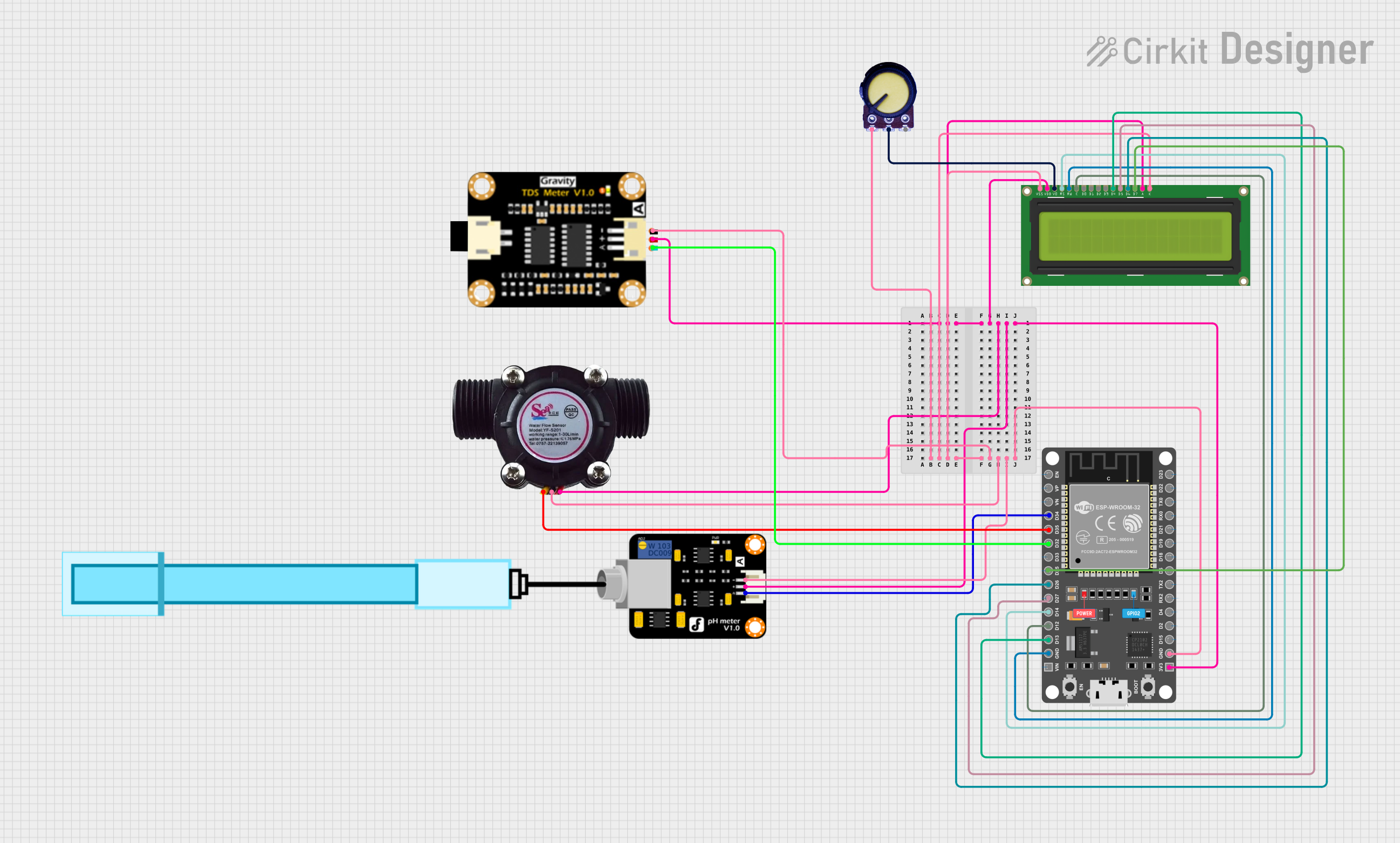
Usage Instructions
How to Use the MKEM0004 in a Circuit
Connect the Pins:
- Connect the VCC pin to a 3.3V or 5V power supply.
- Connect the GND pin to the ground of your circuit.
- Connect the OUT pin to the input of the device or circuit you want to control.
Adjust the Potentiometer:
- Rotate the potentiometer knob to vary the resistance and adjust the output voltage.
- Turning clockwise typically increases the output voltage, while turning counterclockwise decreases it.
Test the Output:
- Use a multimeter to measure the voltage at the OUT pin to ensure it meets your requirements.
Important Considerations and Best Practices
- Power Supply: Ensure the module is powered within its operating voltage range (3.3V to 5V).
- Load Limitations: Do not exceed the module's power rating of 0.5W to avoid damage.
- Stable Connections: Use secure and reliable connections to prevent fluctuations in output voltage.
- Environmental Conditions: Operate the module within the specified temperature range (-10°C to 60°C).
Example: Using the MKEM0004 with an Arduino UNO
The MKEM0004 can be easily interfaced with an Arduino UNO to read the potentiometer's output and control other components. Below is an example code snippet:
// Example code for interfacing the MKEM0004 with an Arduino UNO
// This code reads the potentiometer's output and adjusts the brightness of an LED.

const int potPin = A0;  // Connect the OUT pin of MKEM0004 to Arduino analog pin A0
const int ledPin = 9;   // Connect an LED to digital pin 9 (with a resistor in series)

void setup() {
  pinMode(ledPin, OUTPUT);  // Set the LED pin as an output
  Serial.begin(9600);       // Initialize serial communication for debugging
}

void loop() {
  int potValue = analogRead(potPin);  // Read the potentiometer value (0-1023)
  int ledBrightness = map(potValue, 0, 1023, 0, 255);  // Map to PWM range (0-255)

  analogWrite(ledPin, ledBrightness);  // Adjust LED brightness
  Serial.print("Potentiometer Value: ");  // Print the potentiometer value
  Serial.println(potValue);              // to the Serial Monitor

  delay(100);  // Small delay for stability
}
Troubleshooting and FAQs
Common Issues and Solutions
No Output Voltage:
- Cause: Incorrect wiring or loose connections.
- Solution: Double-check the connections to ensure the VCC, GND, and OUT pins are properly connected.
Fluctuating Output:
- Cause: Unstable power supply or poor connections.
- Solution: Use a stable power source and ensure all connections are secure.
Output Voltage Not Changing:
- Cause: Faulty potentiometer or incorrect adjustment.
- Solution: Verify the potentiometer's functionality by rotating the knob and measuring the output voltage.
Overheating:
- Cause: Exceeding the power rating of 0.5W.
- Solution: Reduce the load on the module and ensure it operates within its specified limits.
FAQs
Q1: Can the MKEM0004 be used with a 12V power supply?
A1: No, the module is designed to operate within a voltage range of 3.3V to 5V. Using a higher voltage may damage the component.
Q2: Is the MKEM0004 suitable for audio applications?
A2: Yes, the module can be used for audio volume control, provided the load does not exceed its power rating.
Q3: How do I clean the potentiometer if it becomes noisy or unresponsive?
A3: Use a contact cleaner spray to clean the potentiometer. Avoid using excessive force when rotating the knob.
Q4: Can I use the MKEM0004 to control a motor?
A4: The module can be used to control the input voltage to a motor driver, but it is not suitable for directly driving a motor due to its power limitations.