How to Use step down 5v: Examples, Pinouts, and Specs
Introduction
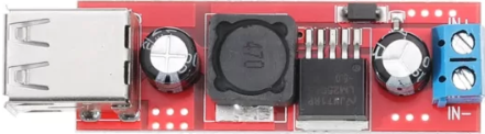
A step-down converter, also known as a buck converter, is an essential component in power management systems. It efficiently reduces a higher input voltage to a stable 5V output, making it ideal for powering 5V devices from higher voltage sources such as batteries, solar panels, or other power supplies. This documentation provides a comprehensive guide to understanding, using, and troubleshooting a 5V step-down converter.
Explore Projects Built with step down 5v


Explore Projects Built with step down 5v
Common Applications and Use Cases
- Powering Microcontrollers: Supplying stable 5V power to microcontrollers like Arduino, Raspberry Pi, etc.
- Battery-Powered Projects: Converting higher battery voltages (e.g., 12V, 24V) to 5V for various electronic components.
- Portable Devices: Ensuring consistent 5V output for portable devices and gadgets.
- Solar Power Systems: Regulating voltage from solar panels to charge 5V devices or batteries.
Technical Specifications
Key Technical Details
| Parameter | Value |
|---|---|
| Input Voltage Range | 6V to 24V |
| Output Voltage | 5V (fixed) |
| Output Current | Up to 3A |
| Efficiency | Up to 95% |
| Switching Frequency | 150 kHz |
| Operating Temperature | -40°C to 85°C |
| Dimensions | 25mm x 20mm x 10mm |
Pin Configuration and Descriptions
| Pin Number | Pin Name | Description |
|---|---|---|
| 1 | VIN | Input voltage (6V to 24V) |
| 2 | GND | Ground |
| 3 | VOUT | Output voltage (5V) |
| 4 | EN | Enable pin (active high, connect to VIN to enable) |
Usage Instructions
How to Use the Component in a Circuit
Connect the Input Voltage:
- Connect the positive terminal of your power source (6V to 24V) to the
VINpin. - Connect the negative terminal of your power source to the
GNDpin.
- Connect the positive terminal of your power source (6V to 24V) to the
Connect the Output Voltage:
- Connect the
VOUTpin to the positive terminal of your 5V device. - Connect the
GNDpin to the ground terminal of your 5V device.
- Connect the
Enable the Converter:
- To enable the converter, connect the
ENpin to theVINpin. If theENpin is left floating or connected to ground, the converter will be disabled.
- To enable the converter, connect the
Important Considerations and Best Practices
- Heat Dissipation: Ensure adequate ventilation or heat sinking if the converter is operating at high currents to prevent overheating.
- Input Voltage Range: Do not exceed the specified input voltage range (6V to 24V) to avoid damaging the converter.
- Load Requirements: Ensure that the connected load does not exceed the maximum output current (3A) to maintain stable operation.
- Noise Reduction: Use appropriate decoupling capacitors close to the input and output pins to minimize noise and voltage ripple.
Example: Connecting to an Arduino UNO
To power an Arduino UNO using a 12V battery and a 5V step-down converter:
- Connect the positive terminal of the 12V battery to the
VINpin of the converter. - Connect the negative terminal of the 12V battery to the
GNDpin of the converter. - Connect the
VOUTpin of the converter to the5Vpin of the Arduino UNO. - Connect the
GNDpin of the converter to theGNDpin of the Arduino UNO. - Connect the
ENpin to theVINpin to enable the converter.
Troubleshooting and FAQs
Common Issues and Solutions
No Output Voltage:
- Check Connections: Ensure all connections are secure and correct.
- Enable Pin: Verify that the
ENpin is connected toVINto enable the converter. - Input Voltage: Confirm that the input voltage is within the specified range (6V to 24V).
Overheating:
- Current Load: Ensure the load current does not exceed 3A.
- Ventilation: Provide adequate ventilation or use a heat sink to dissipate heat.
Output Voltage Fluctuations:
- Decoupling Capacitors: Add decoupling capacitors close to the input and output pins.
- Stable Input Voltage: Ensure the input voltage is stable and within the specified range.
FAQs
Q1: Can I use the step-down converter with a 24V power supply?
- A1: Yes, the converter can handle input voltages up to 24V. Ensure the input voltage does not exceed this limit.
Q2: What happens if I connect the EN pin to ground?
- A2: Connecting the
ENpin to ground will disable the converter, and no output voltage will be generated.
Q3: How can I reduce noise in the output voltage?
- A3: Use appropriate decoupling capacitors (e.g., 100µF electrolytic and 0.1µF ceramic) close to the input and output pins to minimize noise and voltage ripple.
Q4: Is it safe to power my Arduino UNO directly from the 5V output of the converter?
- A4: Yes, it is safe to power the Arduino UNO directly from the 5V output of the converter, as long as the input voltage to the converter is within the specified range.
By following this documentation, users can effectively utilize the 5V step-down converter in their projects, ensuring stable and efficient power management.