How to Use INA226 VI Sensor: Examples, Pinouts, and Specs
Introduction
The INA226 is a high-side current shunt and voltage monitor with an integrated I2C interface. It is designed to measure both current and voltage with high precision, making it ideal for power monitoring applications. The device is widely used in battery management systems, energy monitoring, and industrial equipment where accurate power measurement is critical. Its ability to measure shunt voltage, bus voltage, and calculate power makes it a versatile component for a variety of electronic projects.
Explore Projects Built with INA226 VI Sensor

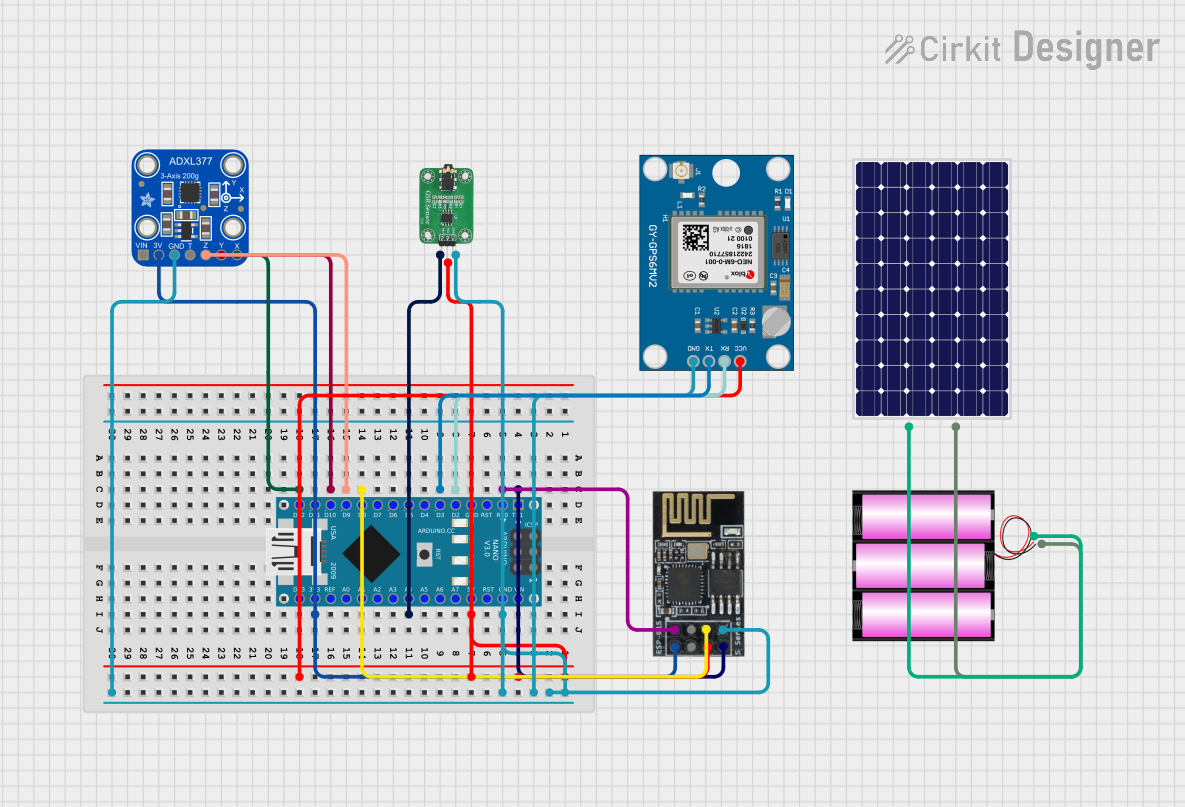
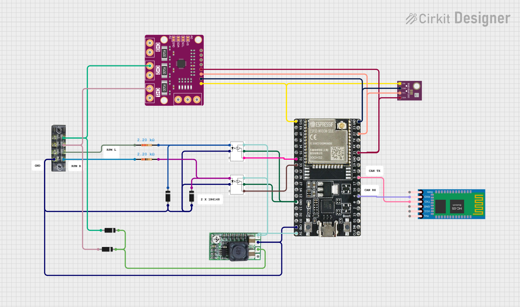
Explore Projects Built with INA226 VI Sensor
Common Applications:
- Battery management systems
- Energy monitoring in IoT devices
- Power supply monitoring
- Industrial automation systems
- Solar power systems
Technical Specifications
The INA226 offers a range of features and specifications that make it a reliable and efficient choice for power monitoring applications.
Key Technical Details:
- Supply Voltage (Vcc): 2.7V to 5.5V
- Bus Voltage Range: 0V to 36V
- Shunt Voltage Range: ±81.92mV
- Current Measurement Range: Determined by the shunt resistor value
- Communication Interface: I2C (up to 1 MHz)
- Resolution: 16-bit ADC
- Operating Temperature Range: -40°C to +125°C
- Power Consumption: 330 µA (typical)
Pin Configuration and Descriptions:
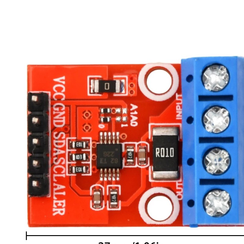
The INA226 is available in a small 10-pin VSSOP package. Below is the pinout and description:
| Pin Number | Pin Name | Description |
|---|---|---|
| 1 | VBUS | Bus voltage input (0V to 36V) |
| 2 | GND | Ground |
| 3 | SCL | I2C clock line |
| 4 | SDA | I2C data line |
| 5 | ALERT | Alert output (programmable threshold) |
| 6 | NC | No connection |
| 7 | NC | No connection |
| 8 | VSHUNT+ | Positive input for shunt voltage measurement |
| 9 | VSHUNT- | Negative input for shunt voltage measurement |
| 10 | VCC | Power supply input (2.7V to 5.5V) |
Usage Instructions
The INA226 is straightforward to use in a circuit, but proper configuration and calibration are essential for accurate measurements.
How to Use the INA226 in a Circuit:
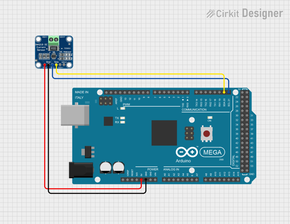
- Power Supply: Connect the VCC pin to a 3.3V or 5V power source and the GND pin to ground.
- Shunt Resistor: Place a precision shunt resistor between the VSHUNT+ and VSHUNT- pins. The value of the resistor determines the current measurement range.
- Voltage Measurement: Connect the VBUS pin to the voltage source you want to monitor (up to 36V).
- I2C Communication: Connect the SCL and SDA pins to the corresponding I2C lines of your microcontroller. Use pull-up resistors (typically 4.7kΩ) on these lines.
- Alert Pin (Optional): The ALERT pin can be configured to trigger when certain thresholds are exceeded. Connect it to a microcontroller GPIO pin if needed.
Important Considerations:
- Shunt Resistor Selection: Choose a low-value, high-precision resistor to minimize power loss while ensuring measurable voltage across the shunt.
- I2C Address: The INA226 has a configurable I2C address, allowing multiple devices on the same bus. Refer to the datasheet for address configuration details.
- Calibration: Perform calibration in software to account for the shunt resistor value and improve measurement accuracy.
Example Code for Arduino UNO:
Below is an example of how to use the INA226 with an Arduino UNO to measure voltage and current:
#include <Wire.h>
#include <Adafruit_INA226.h>

// Create an INA226 object
Adafruit_INA226 ina226;

void setup() {
  Serial.begin(9600); // Initialize serial communication
  while (!Serial) {
    delay(10); // Wait for Serial Monitor to open
  }

  // Initialize the INA226 sensor
  if (!ina226.begin()) {
    Serial.println("Failed to find INA226 chip");
    while (1) {
      delay(10); // Halt if sensor initialization fails
    }
  }
  Serial.println("INA226 initialized successfully");

  // Configure the INA226
  ina226.setCalibration_32V_2A(); // Set calibration for 32V bus and 2A max current
}

void loop() {
  // Read bus voltage
  float busVoltage = ina226.getBusVoltage_V();
  // Read shunt voltage
  float shuntVoltage = ina226.getShuntVoltage_mV();
  // Calculate current
  float current = ina226.getCurrent_mA();
  // Calculate power
  float power = ina226.getPower_mW();

  // Print the measurements
  Serial.print("Bus Voltage: ");
  Serial.print(busVoltage);
  Serial.println(" V");

  Serial.print("Shunt Voltage: ");
  Serial.print(shuntVoltage);
  Serial.println(" mV");

  Serial.print("Current: ");
  Serial.print(current);
  Serial.println(" mA");

  Serial.print("Power: ");
  Serial.print(power);
  Serial.println(" mW");

  delay(1000); // Wait 1 second before the next reading
}
Notes:
- The
Adafruit_INA226library is used in this example. Install it via the Arduino Library Manager. - Adjust the calibration settings (
setCalibration_32V_2A) based on your specific application.
Troubleshooting and FAQs
Common Issues:
No I2C Communication:
- Cause: Incorrect wiring or missing pull-up resistors on the I2C lines.
- Solution: Verify the connections and ensure 4.7kΩ pull-up resistors are present on the SDA and SCL lines.
Inaccurate Measurements:
- Cause: Incorrect shunt resistor value or lack of calibration.
- Solution: Double-check the shunt resistor value and perform software calibration.
Sensor Not Detected:
- Cause: Incorrect I2C address or faulty wiring.
- Solution: Verify the I2C address and ensure proper connections.
Alert Pin Not Functioning:
- Cause: Alert thresholds not configured.
- Solution: Configure the alert thresholds in software using the appropriate library functions.
FAQs:
Q: Can the INA226 measure negative currents?
A: Yes, the INA226 can measure bidirectional currents if configured appropriately.Q: What is the maximum current the INA226 can measure?
A: The maximum current depends on the shunt resistor value and the shunt voltage range (±81.92mV). For example, with a 0.01Ω shunt resistor, the maximum current is ±8.192A.Q: Can I use the INA226 with a 5V microcontroller?
A: Yes, the INA226 supports a supply voltage range of 2.7V to 5.5V, making it compatible with both 3.3V and 5V systems.Q: How do I change the I2C address of the INA226?
A: The I2C address is determined by the A0 and A1 pins. Refer to the datasheet for the address configuration table.
By following this documentation, you can effectively integrate the INA226 into your projects for precise voltage, current, and power measurements.