How to Use Boost Converter: Examples, Pinouts, and Specs
Introduction
A Boost Converter is a type of DC-DC converter that steps up (increases) the input voltage to a higher output voltage while maintaining power balance. It is widely used in applications where the input voltage is lower than the required output voltage. This component is essential in battery-powered devices, renewable energy systems, and portable electronics to enhance efficiency and ensure stable operation.
Explore Projects Built with Boost Converter
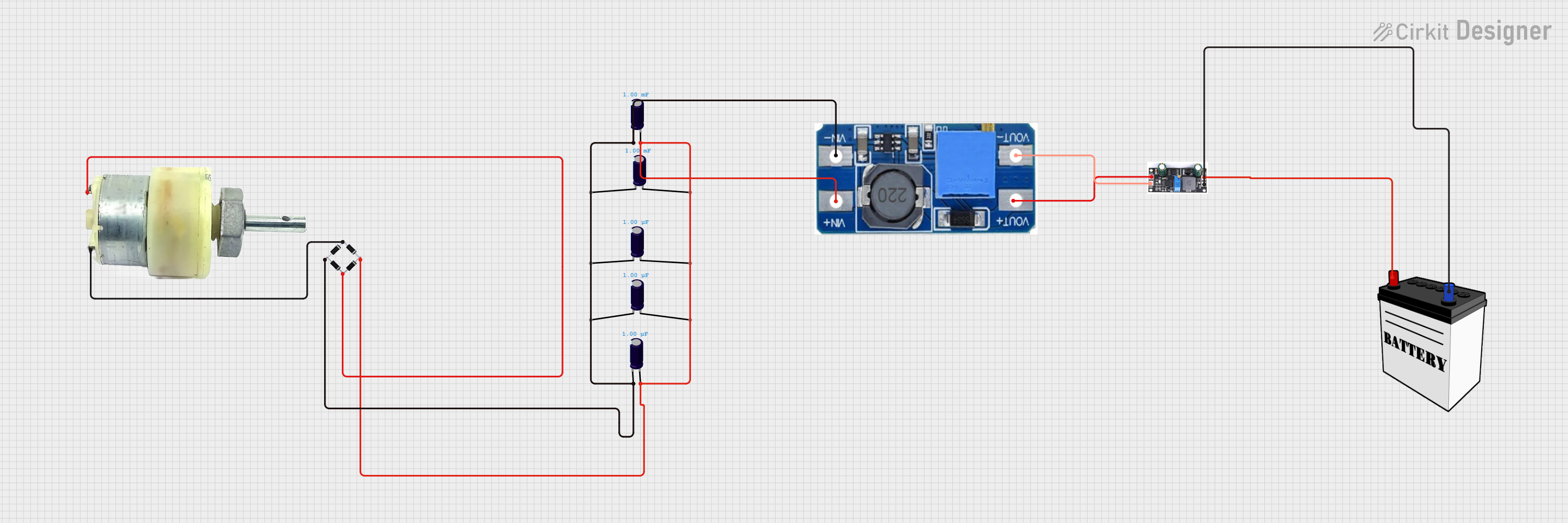


Explore Projects Built with Boost Converter
Common Applications and Use Cases
- Powering high-voltage devices from low-voltage batteries
- Solar power systems to regulate and step up voltage
- LED drivers for consistent brightness
- Electric vehicles and hybrid systems
- Portable chargers and power banks
Technical Specifications
Below are the general technical specifications of a typical Boost Converter. Note that specific values may vary depending on the model and manufacturer.
Key Technical Details
- Input Voltage Range: 2V to 36V (varies by model)
- Output Voltage Range: 5V to 60V (adjustable in some models)
- Output Current: Up to 10A (depending on the design)
- Efficiency: 85% to 95% (depending on load and input/output conditions)
- Switching Frequency: 100 kHz to 1 MHz
- Operating Temperature: -40°C to 85°C
Pin Configuration and Descriptions
The pin configuration of a Boost Converter module typically includes the following:
| Pin Name | Description |
|---|---|
| VIN | Input voltage pin. Connect the lower voltage DC source here. |
| GND | Ground pin. Connect to the ground of the input and output circuits. |
| VOUT | Output voltage pin. Provides the stepped-up voltage. |
| EN (optional) | Enable pin. Used to turn the converter on or off (logic high to enable). |
| ADJ (optional) | Adjustment pin. Allows fine-tuning of the output voltage (in adjustable models). |
Usage Instructions
How to Use the Boost Converter in a Circuit
- Connect the Input Voltage:
- Attach the positive terminal of your DC power source to the VIN pin.
- Connect the negative terminal of the power source to the GND pin.
- Connect the Load:
- Attach the positive terminal of your load to the VOUT pin.
- Connect the negative terminal of your load to the GND pin.
- Adjust the Output Voltage (if applicable):
- For adjustable Boost Converters, use the onboard potentiometer or ADJ pin to set the desired output voltage.
- Use a multimeter to measure the output voltage while adjusting.
- Power On:
- Ensure all connections are secure and power on the input source. The Boost Converter will step up the voltage to the desired level.
Important Considerations and Best Practices
- Input Voltage Range: Ensure the input voltage is within the specified range of the Boost Converter to avoid damage.
- Output Voltage Limit: Do not exceed the maximum output voltage rating of the module.
- Heat Dissipation: High current loads may cause the module to heat up. Use a heatsink or active cooling if necessary.
- Capacitor Placement: Place input and output capacitors close to the module to reduce voltage ripple and improve stability.
- Polarity: Double-check the polarity of all connections to prevent damage to the module or connected devices.
Example: Using a Boost Converter with Arduino UNO
Below is an example of using a Boost Converter to power an Arduino UNO from a 3.7V lithium-ion battery:
- Connect the battery's positive terminal to the VIN pin of the Boost Converter.
- Connect the battery's negative terminal to the GND pin of the Boost Converter.
- Adjust the Boost Converter's output voltage to 5V using the onboard potentiometer.
- Connect the VOUT pin of the Boost Converter to the Arduino's 5V pin.
- Connect the GND pin of the Boost Converter to the Arduino's GND pin.
// Example code for Arduino UNO powered by a Boost Converter
// This code blinks an LED connected to pin 13

void setup() {
  pinMode(13, OUTPUT); // Set pin 13 as an output pin
}

void loop() {
  digitalWrite(13, HIGH); // Turn the LED on
  delay(1000);            // Wait for 1 second
  digitalWrite(13, LOW);  // Turn the LED off
  delay(1000);            // Wait for 1 second
}
Troubleshooting and FAQs
Common Issues and Solutions
No Output Voltage:
- Check the input voltage and ensure it is within the specified range.
- Verify all connections, especially the polarity of VIN and GND.
- Ensure the EN pin (if present) is set to logic high.
Output Voltage is Incorrect:
- For adjustable models, recheck the potentiometer setting or ADJ pin configuration.
- Measure the input voltage to ensure it is stable and sufficient.
Overheating:
- Reduce the load current if it exceeds the module's capacity.
- Add a heatsink or active cooling to the Boost Converter.
High Voltage Ripple:
- Add capacitors with appropriate ratings to the input and output terminals.
- Ensure the wiring is short and properly soldered to minimize resistance.
FAQs
Q: Can I use a Boost Converter to power sensitive electronics?
A: Yes, but ensure the output voltage is stable and within the tolerance range of your device. Adding capacitors can help reduce voltage ripple.
Q: What happens if I reverse the polarity of the input voltage?
A: Reversing the polarity can damage the Boost Converter. Always double-check connections before powering on.
Q: Can I use a Boost Converter with an Arduino for battery-powered projects?
A: Absolutely! A Boost Converter is ideal for stepping up battery voltage to power an Arduino or other microcontrollers.
Q: How do I calculate the efficiency of my Boost Converter?
A: Efficiency can be calculated using the formula:
[
\text{Efficiency} (%) = \left( \frac{\text{Output Power}}{\text{Input Power}} \right) \times 100
]
Measure the input and output voltage and current to determine power values.
By following this documentation, you can effectively integrate a Boost Converter into your projects and troubleshoot common issues.