
How to Use Antenna: Examples, Pinouts, and Specs
 Design with Antenna in Cirkit Designer
Introduction
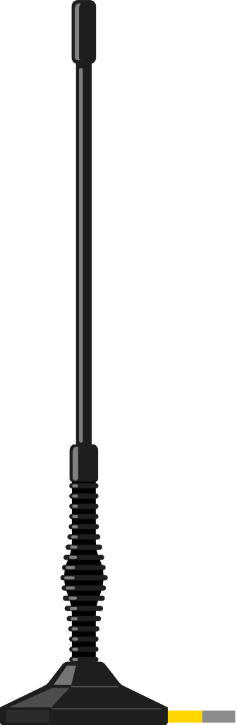
An antenna is a device that converts electrical energy into radio waves and vice versa. It is a critical component in wireless communication systems, enabling the transmission and reception of signals over the air. Antennas come in various shapes and sizes, each designed for specific frequency ranges and applications. They are widely used in devices such as radios, televisions, mobile phones, Wi-Fi routers, and satellite communication systems.
Explore Projects Built with Antenna
 Open Project in Cirkit Designer
 Open Project in Cirkit Designer
 Open Project in Cirkit Designer
 Open Project in Cirkit Designer
Explore Projects Built with Antenna
Open Project in Cirkit DesignerOpen Project in Cirkit DesignerOpen Project in Cirkit DesignerOpen Project in Cirkit DesignerCommon Applications and Use Cases
- Wireless communication (e.g., Wi-Fi, Bluetooth, cellular networks)
- Radio and television broadcasting
- Satellite communication
- Radar systems
- Internet of Things (IoT) devices
- Remote control systems
Technical Specifications
The technical specifications of an antenna vary depending on its type and intended application. Below are general parameters to consider:
| Parameter | Description |
|---|---|
| Frequency Range | The range of frequencies the antenna is designed to transmit or receive. |
| Gain | A measure of how well the antenna directs or receives energy, typically in dBi. |
| Polarization | The orientation of the electromagnetic wave (e.g., linear, circular). |
| Impedance | The resistance to the flow of electrical current, typically 50Ω or 75Ω. |
| Radiation Pattern | The directional distribution of radiated energy. |
| VSWR (Voltage Standing Wave Ratio) | Indicates how efficiently power is transmitted or received. |
| Connector Type | The type of connector used to interface with the antenna (e.g., SMA, RP-SMA). |
Example Pin Configuration (for Active Antennas)
Some antennas, such as active GPS antennas, may have additional pins for power and signal. Below is an example configuration:
| Pin | Name | Description |
|---|---|---|
| 1 | Signal Output | Outputs the received signal to the connected device. |
| 2 | VCC | Power supply input for active antennas. |
| 3 | GND | Ground connection. |
Usage Instructions
How to Use an Antenna in a Circuit
- Select the Appropriate Antenna: Choose an antenna that matches the frequency range and impedance of your system.
- Connect the Antenna:
- For passive antennas, connect the signal pin to the RF input/output of your device.
- For active antennas, connect the VCC and GND pins to the appropriate power supply.
- Position the Antenna: Place the antenna in a location with minimal obstructions to maximize signal strength.
- Match Impedance: Use a matching network or ensure the antenna's impedance matches the system's impedance to minimize signal loss.
- Test the System: Verify the antenna's performance using tools like a spectrum analyzer or VSWR meter.
Important Considerations and Best Practices
- Avoid Interference: Keep the antenna away from metal objects and other sources of electromagnetic interference.
- Orientation: Align the antenna's polarization with the transmitting or receiving device for optimal performance.
- Cable Length: Minimize cable length to reduce signal loss.
- Environmental Factors: Consider weatherproofing for outdoor antennas.
Example: Using an Antenna with an Arduino UNO
Below is an example of connecting a 433 MHz RF module with an antenna to an Arduino UNO for wireless communication:
Circuit Diagram
- Connect the antenna to the RF module's antenna pin.
- Connect the RF module's data pin to Arduino's digital pin 7.
- Provide power (VCC and GND) to the RF module.
Arduino Code
// Example code for transmitting data using a 433 MHz RF module and antenna
#include <VirtualWire.h> // Include the VirtualWire library for RF communication

void setup() {
  vw_setup(2000); // Set the transmission speed to 2000 bits per second
  vw_set_tx_pin(7); // Set the data pin for transmission
}

void loop() {
  const char *message = "Hello, World!"; // Message to be transmitted
  vw_send((uint8_t *)message, strlen(message)); // Send the message
  vw_wait_tx(); // Wait for the transmission to complete
  delay(1000); // Wait 1 second before sending the next message
}
Troubleshooting and FAQs
Common Issues
Weak Signal Strength:
- Cause: Poor antenna placement or interference.
- Solution: Reposition the antenna to a higher or less obstructed location.
High VSWR:
- Cause: Impedance mismatch between the antenna and the system.
- Solution: Use an impedance matching network or a different antenna.
No Signal Reception:
- Cause: Incorrect frequency range or damaged antenna.
- Solution: Verify the antenna's frequency range and inspect for physical damage.
Intermittent Signal:
- Cause: Loose connections or environmental interference.
- Solution: Secure all connections and minimize interference sources.
FAQs
Q: Can I use any antenna with my device?
- A: No, the antenna must match the frequency range and impedance of your device.
Q: How do I know if my antenna is working properly?
- A: Use a spectrum analyzer or VSWR meter to test the antenna's performance.
Q: Can I extend the antenna cable?
- A: Yes, but longer cables can introduce signal loss. Use high-quality, low-loss cables.
Q: What is the difference between active and passive antennas?
- A: Active antennas have built-in amplifiers and require power, while passive antennas do not.
This documentation provides a comprehensive guide to understanding and using antennas effectively in various applications.