
How to Use xt-60: Examples, Pinouts, and Specs
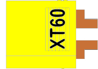
 Design with xt-60 in Cirkit Designer
Introduction
The XT60 is a high-current connector widely used in RC (radio-controlled) applications. It is designed to handle up to 60A of continuous current, making it suitable for high-power systems. The XT60 features a secure, polarized design that prevents reverse polarity connections, ensuring safe and reliable operation. Its robust construction and gold-plated contacts provide excellent conductivity and durability, even under demanding conditions.
Explore Projects Built with xt-60
 Open Project in Cirkit Designer
 Open Project in Cirkit Designer
 Open Project in Cirkit Designer
 Open Project in Cirkit Designer
Explore Projects Built with xt-60
Open Project in Cirkit DesignerOpen Project in Cirkit DesignerOpen Project in Cirkit DesignerOpen Project in Cirkit DesignerCommon Applications and Use Cases
- Battery connections in RC vehicles, drones, and airplanes
- Electronic speed controllers (ESCs) in RC systems
- High-current power delivery in DIY electronics projects
- Robotics and other high-power applications requiring secure connections
Technical Specifications
The XT60 connector is designed to meet the needs of high-current applications while maintaining a compact and lightweight form factor. Below are the key technical details:
| Specification | Value |
|---|---|
| Maximum Current Rating | 60A (continuous) |
| Voltage Rating | Up to 500V DC |
| Contact Material | Gold-plated brass |
| Housing Material | Nylon (heat-resistant) |
| Operating Temperature | -20°C to 120°C |
| Connector Type | Male and Female (pair) |
| Wire Gauge Compatibility | 12 AWG to 10 AWG |
| Dimensions | 21.5mm x 16mm x 8mm |
| Weight | ~7g per pair |
Pin Configuration and Descriptions
The XT60 connector consists of two main pins: positive (+) and negative (-). These pins are polarized to prevent incorrect connections. Below is the pin configuration:
| Pin | Description |
|---|---|
| Positive | Connects to the positive terminal of the power source (e.g., battery). |
| Negative | Connects to the negative terminal of the power source (e.g., battery). |
Usage Instructions
How to Use the XT60 Connector in a Circuit
- Prepare the Wires: Strip the insulation from the ends of the wires you intend to connect to the XT60. Ensure the exposed wire length is appropriate for soldering (approximately 3-5mm).
- Tin the Wires: Apply a small amount of solder to the exposed wire ends to make the soldering process easier and ensure a strong connection.
- Solder the Wires to the XT60:
- Heat the solder cup of the XT60 pin with a soldering iron.
- Insert the tinned wire into the solder cup while applying heat.
- Add solder to fill the cup and secure the wire.
- Repeat for both the positive and negative pins.
- Check Polarity: Double-check the polarity of the connections to ensure the positive wire is connected to the positive pin and the negative wire to the negative pin.
- Assemble the Connector: Once the wires are soldered, slide the heat-resistant housing over the pins to complete the assembly.
Important Considerations and Best Practices
- Avoid Overheating: Excessive heat during soldering can damage the nylon housing. Use a soldering iron with a temperature of around 350°C and work quickly.
- Use Heat Shrink Tubing: For added safety, apply heat shrink tubing over the soldered connections to insulate and protect them.
- Check for Secure Connections: Ensure the wires are firmly soldered and there is no loose connection.
- Match Connectors: Always use XT60 connectors with their corresponding male or female counterpart to ensure a proper fit.
Example: Connecting an XT60 to an Arduino UNO
While the XT60 is not directly connected to an Arduino UNO, it can be used to supply power to the Arduino through a voltage regulator or power distribution board. Below is an example of how to use an XT60 connector to power an Arduino UNO:
// Example: Powering an Arduino UNO using an XT60 connector
// Ensure the XT60 is connected to a battery and a voltage regulator
// that outputs 5V (regulated) to the Arduino's 5V pin.

void setup() {
  // Initialize any peripherals connected to the Arduino
  pinMode(13, OUTPUT); // Example: Set pin 13 as an output
}

void loop() {
  // Blink the onboard LED to confirm the Arduino is powered
  digitalWrite(13, HIGH); // Turn the LED on
  delay(1000);            // Wait for 1 second
  digitalWrite(13, LOW);  // Turn the LED off
  delay(1000);            // Wait for 1 second
}
Troubleshooting and FAQs
Common Issues and Solutions
Loose Connections:
- Issue: The wires are not securely soldered to the XT60 pins.
- Solution: Re-solder the connections, ensuring the solder fully fills the cups and the wires are firmly attached.
Overheating During Soldering:
- Issue: The nylon housing melts or deforms during soldering.
- Solution: Use a soldering iron with a controlled temperature (around 350°C) and minimize the time spent applying heat.
Reverse Polarity Connection:
- Issue: The XT60 is connected with reversed polarity, potentially damaging the circuit.
- Solution: Always double-check the polarity before connecting the XT60. The connector's polarized design helps prevent this issue.
Connector Fit Issues:
- Issue: The male and female XT60 connectors do not fit together properly.
- Solution: Ensure the connectors are genuine XT60 parts and free from debris or damage.
FAQs
Q: Can the XT60 handle currents higher than 60A?
A: The XT60 is rated for 60A continuous current. While it may handle short bursts of higher current, exceeding this rating for extended periods can cause overheating and damage.
Q: Is the XT60 waterproof?
A: No, the XT60 is not waterproof. If used in environments where water exposure is possible, additional waterproofing measures (e.g., heat shrink tubing or silicone sealant) should be applied.
Q: Can I use the XT60 with smaller gauge wires?
A: Yes, but smaller gauge wires may not fully utilize the XT60's current-carrying capacity. Ensure the wires are securely soldered and insulated.
Q: Are XT60 connectors compatible with XT90 connectors?
A: No, XT60 and XT90 connectors are not physically compatible due to differences in size and design. Use the appropriate connector type for your application.