How to Use orange led 5: Examples, Pinouts, and Specs

Introduction
The Orange LED 5 (Manufacturer: Shankar, Part ID: 001.4) is a 5mm orange light-emitting diode (LED) designed to emit bright orange light when a suitable current flows through it. This LED is widely used in electronic circuits for visual indicators, status displays, and decorative lighting. Its compact size and low power consumption make it ideal for a variety of applications, including hobby projects, industrial equipment, and consumer electronics.
Explore Projects Built with orange led 5

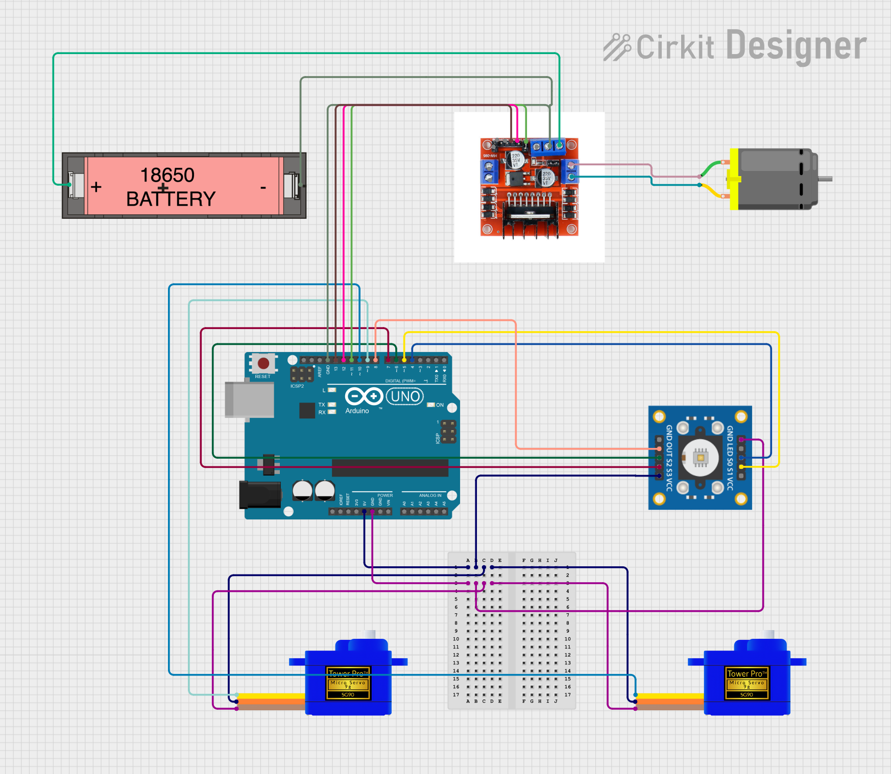
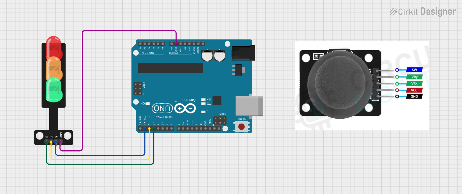
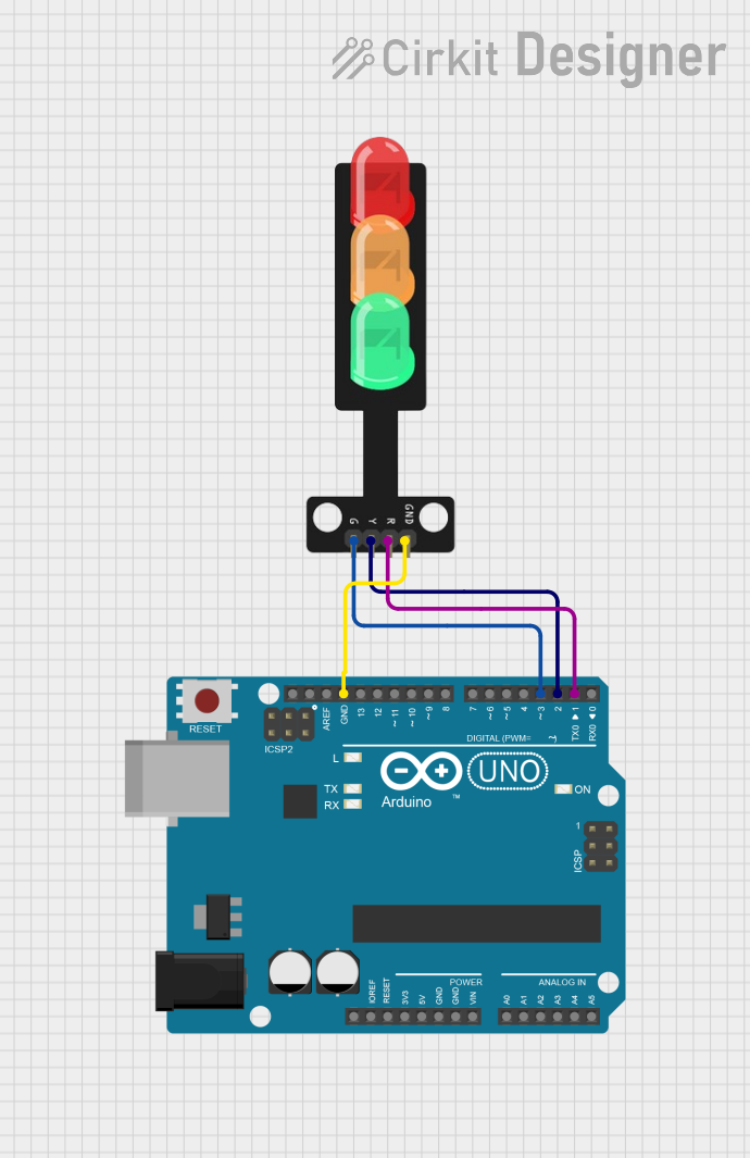
Explore Projects Built with orange led 5
Common Applications
- Power and status indicators
- Signal and warning lights
- Decorative and ambient lighting
- DIY electronics and Arduino projects
- Displays and signage
Technical Specifications
Key Specifications
| Parameter | Value |
|---|---|
| Manufacturer | Shankar |
| Part ID | 001.4 |
| LED Type | 5mm Orange LED |
| Forward Voltage (Vf) | 2.0V to 2.2V |
| Forward Current (If) | 20mA (typical) |
| Maximum Current (If max) | 30mA |
| Wavelength | 600nm to 610nm (orange light) |
| Viewing Angle | 20° to 30° |
| Operating Temperature | -40°C to +85°C |
| Package Type | Through-hole |
Pin Configuration
The Orange LED 5 has two pins: the anode (positive) and the cathode (negative). The longer pin is the anode, and the shorter pin is the cathode.
| Pin Name | Description |
|---|---|
| Anode | Positive terminal (connect to +V) |
| Cathode | Negative terminal (connect to GND) |
Usage Instructions
How to Use the Orange LED 5 in a Circuit
Determine the Resistor Value: To prevent damage to the LED, always use a current-limiting resistor in series with the LED. The resistor value can be calculated using Ohm's Law: [ R = \frac{V_{supply} - V_f}{I_f} ]
- (V_{supply}): Supply voltage
- (V_f): Forward voltage of the LED (2.0V to 2.2V)
- (I_f): Desired forward current (typically 20mA)
For example, if (V_{supply} = 5V) and (V_f = 2.1V), the resistor value is: [ R = \frac{5V - 2.1V}{0.02A} = 145\Omega ] Use the nearest standard resistor value (e.g., 150Ω).
Connect the LED:
- Connect the anode to the positive voltage supply through the resistor.
- Connect the cathode to ground (GND).
Power the Circuit: Apply the supply voltage. The LED will emit orange light if connected correctly.
Important Considerations
- Polarity: LEDs are polarized components. Reversing the polarity may damage the LED.
- Current Limiting: Always use a resistor to limit the current through the LED.
- Heat Dissipation: Avoid exceeding the maximum current rating to prevent overheating.
- Viewing Angle: Position the LED appropriately for optimal visibility.
Example: Connecting to an Arduino UNO
The Orange LED 5 can be easily interfaced with an Arduino UNO for various projects. Below is an example of how to blink the LED using Arduino:
Circuit Diagram
- Connect the anode of the LED to Arduino digital pin 13 through a 220Ω resistor.
- Connect the cathode of the LED to the Arduino GND pin.
Arduino Code
// Blink an Orange LED connected to pin 13
// Ensure a 220Ω resistor is used to limit current

void setup() {
  pinMode(13, OUTPUT); // Set pin 13 as an output
}

void loop() {
  digitalWrite(13, HIGH); // Turn the LED on
  delay(1000);            // Wait for 1 second
  digitalWrite(13, LOW);  // Turn the LED off
  delay(1000);            // Wait for 1 second
}
Troubleshooting and FAQs
Common Issues
LED Does Not Light Up:
Cause: Incorrect polarity.
Solution: Ensure the anode is connected to the positive voltage and the cathode to ground.
Cause: No current-limiting resistor.
Solution: Add a resistor in series with the LED to limit the current.
LED is Dim:
- Cause: Resistor value too high.
- Solution: Recalculate the resistor value for the desired brightness.
LED Burns Out:
- Cause: Excessive current.
- Solution: Use a resistor to limit the current to 20mA.
Flickering LED:
- Cause: Unstable power supply.
- Solution: Use a stable power source or add a capacitor to smooth the voltage.
FAQs
Q: Can I use the Orange LED 5 without a resistor?
A: No, using the LED without a resistor may cause it to draw excessive current and burn out.Q: What is the maximum voltage I can apply to the LED?
A: The LED itself has a forward voltage of 2.0V to 2.2V. Use a resistor to limit the current when using higher supply voltages.Q: Can I use this LED with a 3.3V microcontroller?
A: Yes, but ensure you calculate the appropriate resistor value for the 3.3V supply.Q: Is the Orange LED 5 suitable for outdoor use?
A: The LED can operate in temperatures from -40°C to +85°C, but additional protection may be needed for outdoor environments.
This concludes the documentation for the Orange LED 5.