How to Use Grove RGB LED: Examples, Pinouts, and Specs
Introduction
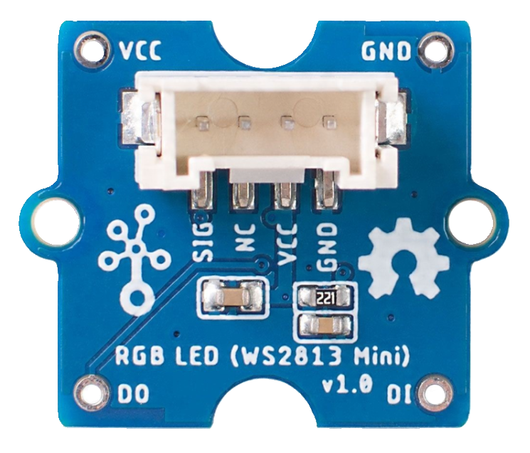
The Grove RGB LED (WS2813 mini), manufactured by Seeeduino, is a versatile multicolor LED capable of emitting red, green, and blue light. By mixing these primary colors, it can produce a wide spectrum of colors, making it ideal for applications requiring dynamic lighting effects. This component is commonly used in projects such as visual indicators, decorative lighting, and displays.
The Grove RGB LED is based on the WS2813 mini, a smart RGB LED with an integrated control circuit. It supports daisy-chaining multiple LEDs for creating complex lighting patterns and is compatible with microcontrollers like Arduino.
Explore Projects Built with Grove RGB LED
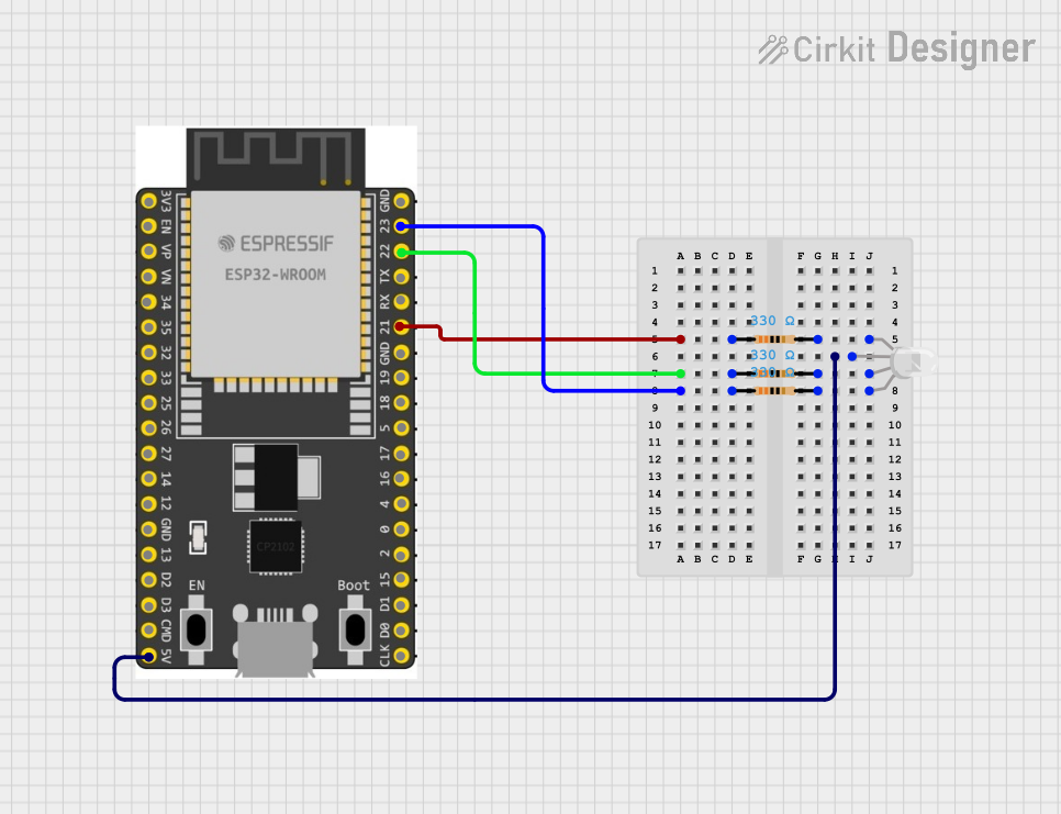
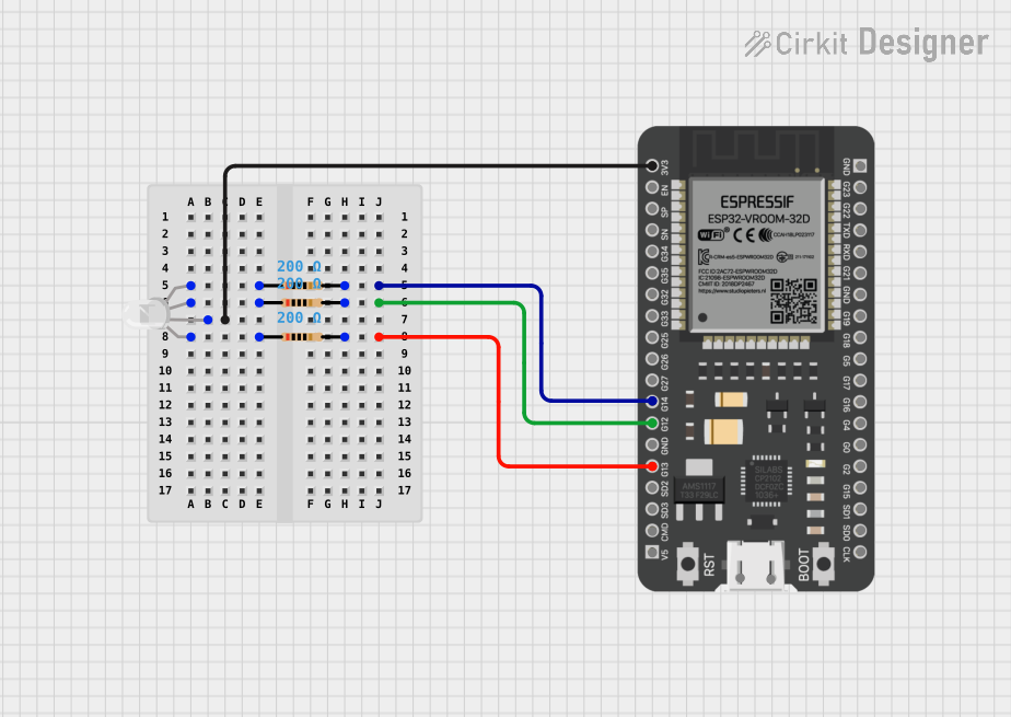
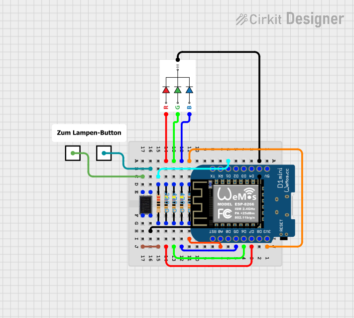

Explore Projects Built with Grove RGB LED
Technical Specifications
Below are the key technical details of the Grove RGB LED (WS2813 mini):
| Parameter | Value |
|---|---|
| Operating Voltage | 3.3V to 5.5V |
| Operating Current | 1mA (idle), up to 60mA (full RGB) |
| Communication Protocol | Single-wire (WS2813 protocol) |
| LED Type | RGB (Red, Green, Blue) |
| Brightness Levels | 256 levels per color channel |
| Daisy-Chaining Support | Yes |
| Operating Temperature | -25°C to 80°C |
Pin Configuration
The Grove RGB LED module has a 4-pin interface. The pinout is as follows:
| Pin | Name | Description |
|---|---|---|
| 1 | VCC | Power supply (3.3V to 5.5V) |
| 2 | GND | Ground |
| 3 | DIN | Data input (control signal from microcontroller) |
| 4 | DOUT | Data output (to the next LED in the chain, if any) |
Usage Instructions
How to Use the Grove RGB LED in a Circuit
- Power Supply: Connect the VCC pin to a 3.3V or 5V power source and the GND pin to ground.
- Data Input: Connect the DIN pin to a digital output pin of your microcontroller (e.g., Arduino).
- Daisy-Chaining: If using multiple LEDs, connect the DOUT pin of the first LED to the DIN pin of the next LED.
- Resistor and Capacitor: For stable operation, place a 330Ω resistor between the microcontroller's data pin and the DIN pin. Additionally, use a 100µF capacitor across VCC and GND to reduce power supply noise.
Arduino Example Code
Below is an example of how to control the Grove RGB LED using an Arduino UNO and the Adafruit NeoPixel library:
#include <Adafruit_NeoPixel.h>

// Define the pin connected to the DIN pin of the Grove RGB LED
#define LED_PIN 6

// Define the number of LEDs in the chain (1 in this case)
#define NUM_LEDS 1

// Create a NeoPixel object
Adafruit_NeoPixel strip = Adafruit_NeoPixel(NUM_LEDS, LED_PIN, NEO_GRB + NEO_KHZ800);

void setup() {
  strip.begin();  // Initialize the NeoPixel library
  strip.show();   // Turn off all LEDs initially
}

void loop() {
  // Set the LED to red
  strip.setPixelColor(0, strip.Color(255, 0, 0)); // Red: 255, Green: 0, Blue: 0
  strip.show();  // Update the LED
  delay(1000);   // Wait for 1 second

  // Set the LED to green
  strip.setPixelColor(0, strip.Color(0, 255, 0)); // Red: 0, Green: 255, Blue: 0
  strip.show();
  delay(1000);

  // Set the LED to blue
  strip.setPixelColor(0, strip.Color(0, 0, 255)); // Red: 0, Green: 0, Blue: 255
  strip.show();
  delay(1000);

  // Turn off the LED
  strip.setPixelColor(0, strip.Color(0, 0, 0)); // All colors off
  strip.show();
  delay(1000);
}
Important Considerations and Best Practices
- Power Supply: Ensure the power supply can handle the current requirements of all LEDs in the chain.
- Signal Integrity: Use a resistor (330Ω) on the data line to prevent signal reflections and noise.
- Capacitor: Place a 100µF capacitor across VCC and GND to stabilize the power supply.
- Daisy-Chaining: When chaining multiple LEDs, ensure the DOUT of one LED is connected to the DIN of the next.
Troubleshooting and FAQs
Common Issues and Solutions
LED Not Lighting Up:
- Check the power supply voltage (3.3V to 5.5V).
- Verify the connections to the DIN and GND pins.
- Ensure the microcontroller is sending data to the correct pin.
Incorrect Colors Displayed:
- Confirm the data format (NEO_GRB) matches the LED's configuration.
- Check for loose or incorrect wiring.
Flickering or Unstable Operation:
- Add a 100µF capacitor across VCC and GND.
- Use a 330Ω resistor on the data line to improve signal quality.
Daisy-Chained LEDs Not Working:
- Verify the DOUT of one LED is connected to the DIN of the next.
- Ensure the microcontroller's data pin can handle the timing requirements for multiple LEDs.
FAQs
Can I use the Grove RGB LED with a 3.3V microcontroller? Yes, the Grove RGB LED operates with both 3.3V and 5V logic levels.
How many LEDs can I daisy-chain? The number of LEDs depends on the power supply capacity and the microcontroller's memory. For Arduino UNO, up to 500 LEDs are typically supported.
Do I need an external library to control the LED? Yes, the Adafruit NeoPixel library is recommended for controlling the Grove RGB LED.
By following this documentation, you can effectively integrate the Grove RGB LED into your projects and troubleshoot common issues.