How to Use LMP91000: Examples, Pinouts, and Specs
Introduction
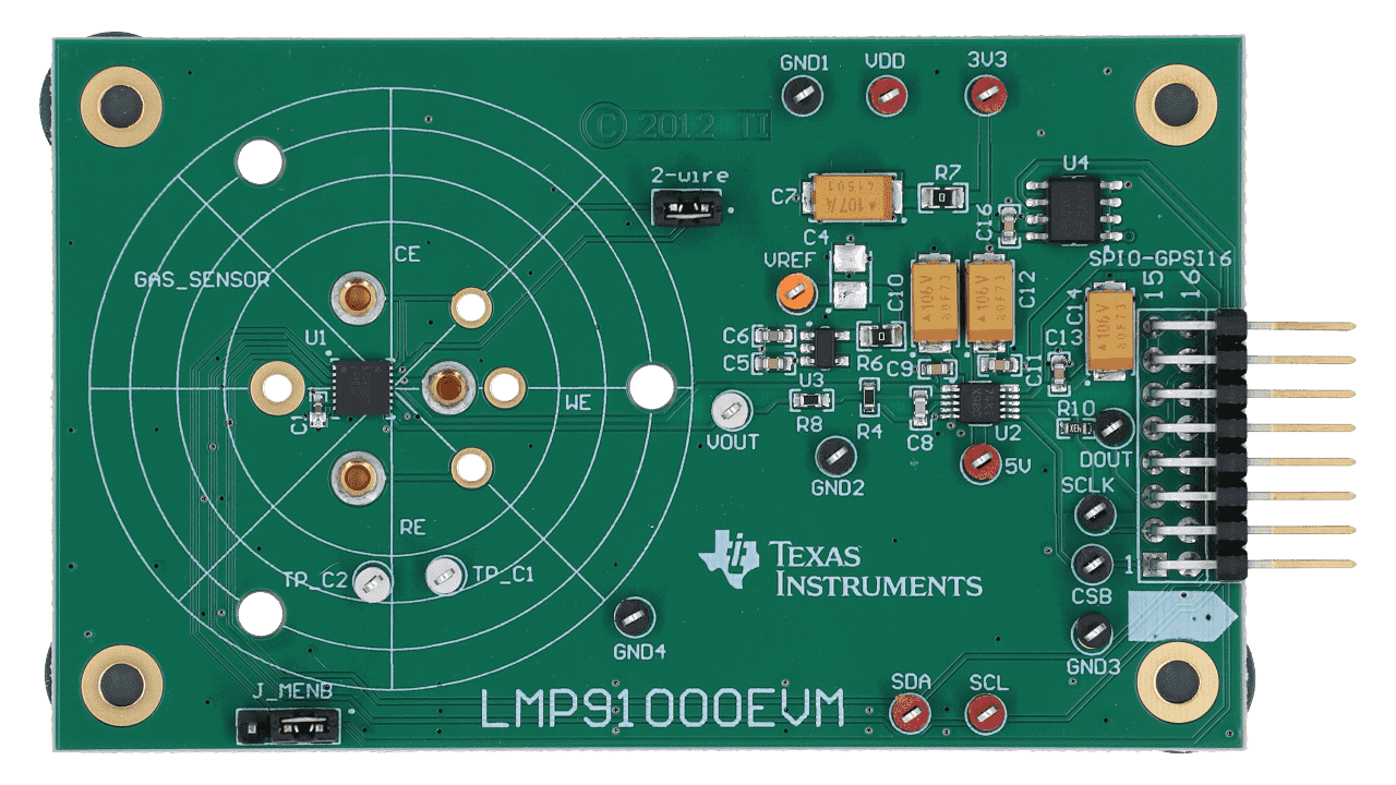
The LMP91000 is a low-power, high-performance potentiostat designed by Texas Instruments for use in electrochemical sensor applications. It integrates a programmable gain amplifier (PGA), a reference voltage output, and configurable bias settings, making it highly versatile for interfacing with a wide range of electrochemical sensors, such as gas sensors, pH sensors, and amperometric sensors.
Explore Projects Built with LMP91000


Explore Projects Built with LMP91000
Common Applications and Use Cases
- Environmental monitoring (e.g., gas detection, air quality sensors)
- Medical diagnostics (e.g., blood glucose monitoring, lactate sensors)
- Industrial process control (e.g., chemical analysis, corrosion monitoring)
- Research and development in electrochemical sensing
The LMP91000 is particularly valued for its low power consumption, making it suitable for portable and battery-powered devices.
Technical Specifications
Key Technical Details
| Parameter | Value |
|---|---|
| Supply Voltage (VDD) | 2.7V to 5.25V |
| Operating Current | 10 µA (typical) |
| Temperature Range | -40°C to +85°C |
| Programmable Gain Amplifier | 2.75 kΩ to 350 kΩ |
| Reference Voltage Output | Programmable (20% to 80% of VDD) |
| Sensor Bias Voltage | Programmable (-24% to +24% of VDD) |
| Communication Interface | I²C |
| Package Type | WSON-14 (4mm x 4mm) |
Pin Configuration and Descriptions
The LMP91000 is available in a 14-pin WSON package. Below is the pinout and description:
| Pin Number | Pin Name | Description |
|---|---|---|
| 1 | VDD | Power supply input (2.7V to 5.25V). |
| 2 | VREF | Reference voltage output for the sensor. |
| 3 | C1 | External capacitor connection for internal filtering. |
| 4 | C2 | External capacitor connection for internal filtering. |
| 5 | VOUT | Output voltage from the potentiostat circuit. |
| 6 | TIA OUT | Transimpedance amplifier output. |
| 7 | CE | Counter electrode connection for the electrochemical sensor. |
| 8 | RE | Reference electrode connection for the electrochemical sensor. |
| 9 | WE | Working electrode connection for the electrochemical sensor. |
| 10 | GND | Ground connection. |
| 11 | SDA | I²C data line for communication. |
| 12 | SCL | I²C clock line for communication. |
| 13 | ADDR | I²C address selection pin. |
| 14 | NC | No connection (leave unconnected). |
Usage Instructions
How to Use the LMP91000 in a Circuit
- Power Supply: Connect the VDD pin to a regulated power supply (2.7V to 5.25V) and GND to the ground.
- Sensor Connections:
- Connect the CE, RE, and WE pins to the counter, reference, and working electrodes of the electrochemical sensor, respectively.
- Reference Voltage: Use the VREF pin to provide a stable reference voltage to the sensor. This voltage can be programmed via the I²C interface.
- External Capacitors: Connect capacitors to the C1 and C2 pins as specified in the datasheet for proper filtering.
- I²C Communication: Use the SDA and SCL pins to communicate with the LMP91000 via an I²C master device (e.g., a microcontroller or Arduino).
Important Considerations and Best Practices
- Sensor Bias Configuration: Configure the sensor bias voltage and gain settings via the I²C interface to match the requirements of your specific sensor.
- Power Consumption: The LMP91000 is optimized for low power consumption, but ensure proper power management in battery-powered applications.
- PCB Layout: Minimize noise by placing decoupling capacitors close to the VDD and GND pins. Keep traces to the sensor electrodes as short as possible.
- Startup Sequence: Ensure the power supply is stable before initializing the I²C communication.
Example: Connecting the LMP91000 to an Arduino UNO
Below is an example of how to interface the LMP91000 with an Arduino UNO using I²C communication:
#include <Wire.h> // Include the Wire library for I²C communication

#define LMP91000_I2C_ADDR 0x48 // Default I²C address of the LMP91000

void setup() {
  Wire.begin(); // Initialize I²C communication
  Serial.begin(9600); // Initialize serial communication for debugging

  // Configure the LMP91000
  Wire.beginTransmission(LMP91000_I2C_ADDR);
  Wire.write(0x10); // Write to the TIACN register (Transimpedance amplifier control)
  Wire.write(0x03); // Set gain to 7kΩ and RLOAD to 10Ω
  Wire.endTransmission();

  Serial.println("LMP91000 configured successfully.");
}

void loop() {
  // Example: Read a register from the LMP91000
  Wire.beginTransmission(LMP91000_I2C_ADDR);
  Wire.write(0x00); // Point to the STATUS register
  Wire.endTransmission();

  Wire.requestFrom(LMP91000_I2C_ADDR, 1); // Request 1 byte from the STATUS register
  if (Wire.available()) {
    byte status = Wire.read();
    Serial.print("STATUS Register: 0x");
    Serial.println(status, HEX);
  }

  delay(1000); // Wait for 1 second before the next read
}
Troubleshooting and FAQs
Common Issues and Solutions
No Output from the Sensor:
- Ensure the sensor is properly connected to the CE, RE, and WE pins.
- Verify that the sensor bias voltage and gain settings are correctly configured via I²C.
I²C Communication Fails:
- Check the connections to the SDA and SCL pins.
- Ensure pull-up resistors (typically 4.7kΩ) are connected to the SDA and SCL lines.
- Verify the I²C address of the LMP91000 (default is 0x48).
High Noise in Output:
- Ensure proper decoupling capacitors are placed near the VDD and GND pins.
- Minimize the length of traces connecting the sensor electrodes to the LMP91000.
Incorrect Reference Voltage:
- Verify the VREF configuration via I²C.
- Ensure the power supply voltage (VDD) is stable and within the specified range.
FAQs
Q: Can the LMP91000 be used with a 3.3V microcontroller?
A: Yes, the LMP91000 operates with a supply voltage as low as 2.7V, making it compatible with 3.3V systems.
Q: What types of sensors are compatible with the LMP91000?
A: The LMP91000 supports a wide range of electrochemical sensors, including amperometric, potentiometric, and voltammetric sensors.
Q: How do I change the I²C address of the LMP91000?
A: The I²C address can be modified by configuring the ADDR pin. Refer to the datasheet for specific address selection options.
This documentation provides a comprehensive guide to understanding, using, and troubleshooting the LMP91000 potentiostat. For further details, refer to the official Texas Instruments datasheet.