How to Use WaterFlow: Examples, Pinouts, and Specs
Introduction
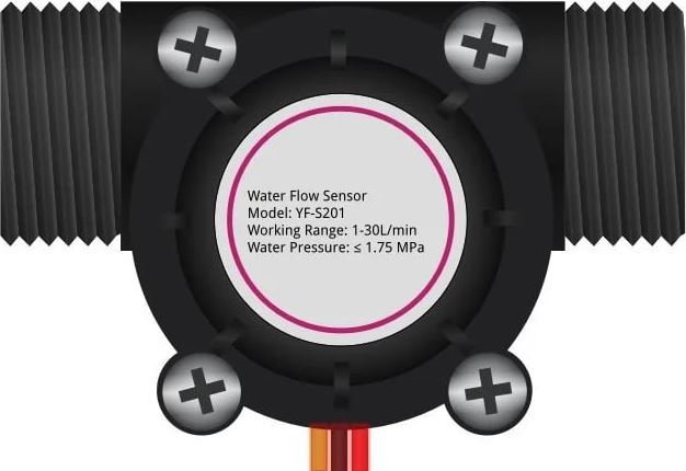
The WaterFlow sensor is a device used to measure or control the flow of water in a system. It operates by detecting the rate of water passing through it, typically using a turbine or similar mechanism. This component is widely utilized in applications such as irrigation systems, plumbing, and industrial processes to ensure proper water management and prevent wastage. Its ability to provide real-time flow data makes it an essential tool for monitoring and automation.
Common applications and use cases:
- Smart irrigation systems for agriculture and gardening
- Water usage monitoring in residential and commercial plumbing
- Industrial process control and automation
- Leak detection and prevention systems
- Water filtration and purification systems
Explore Projects Built with WaterFlow
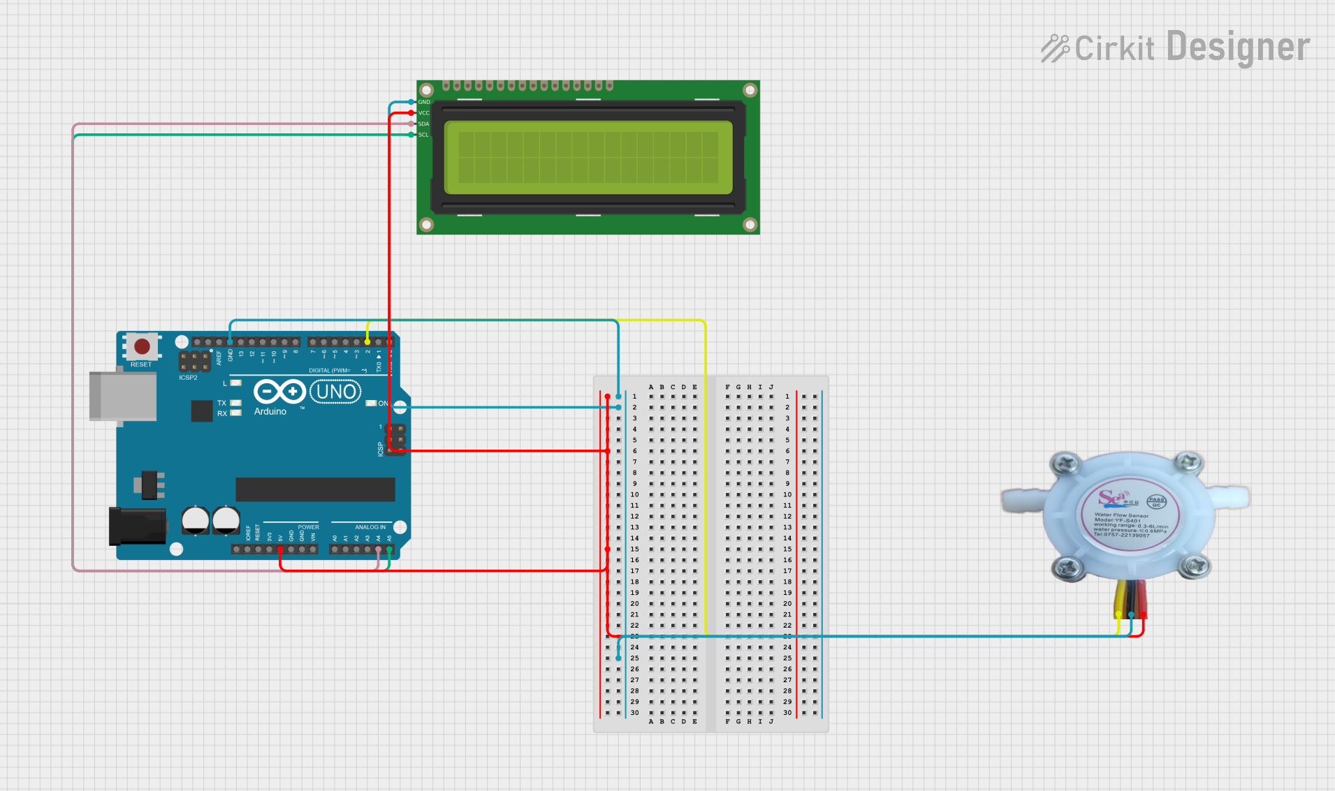
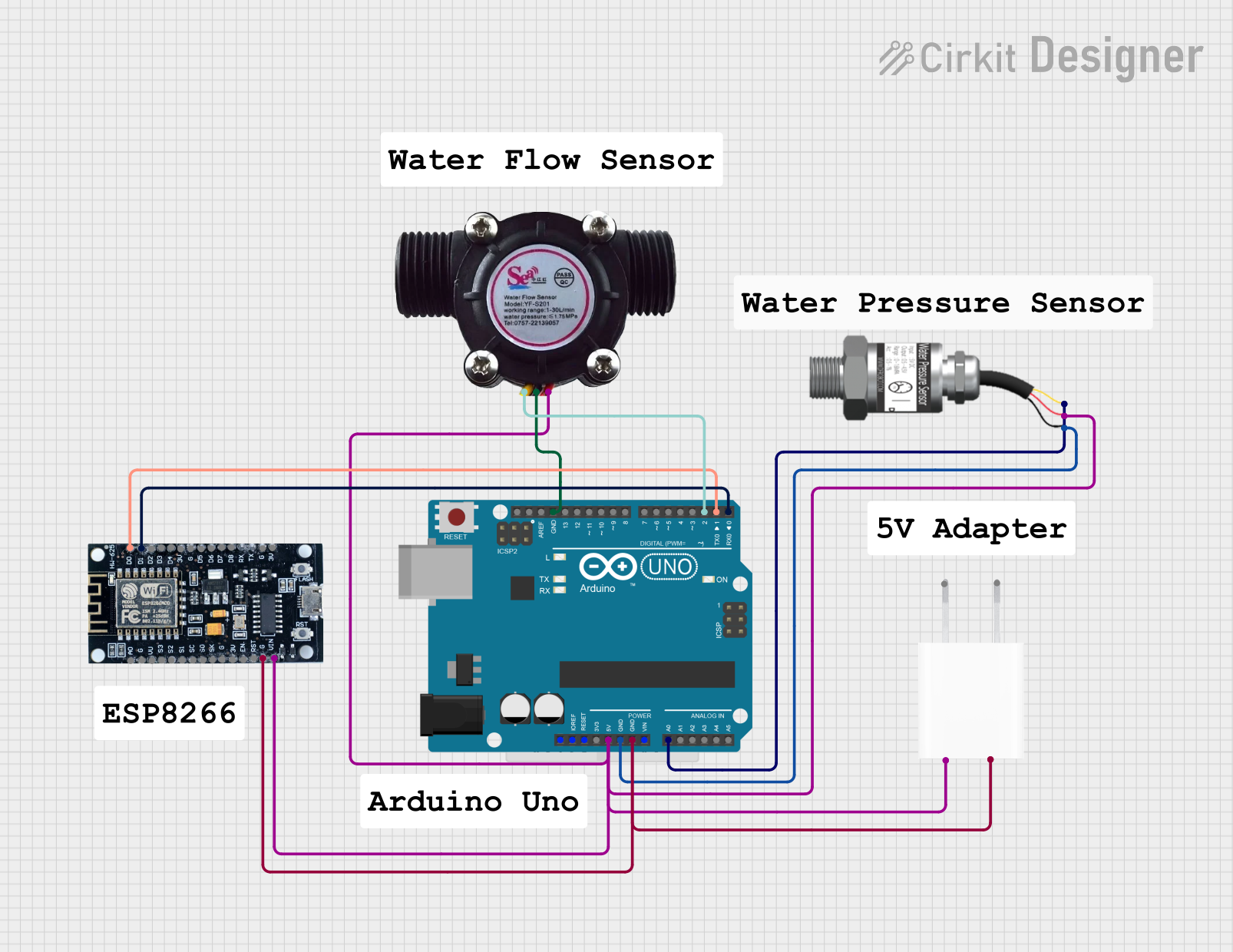
Explore Projects Built with WaterFlow
Technical Specifications
Below are the key technical details for a typical WaterFlow sensor:
| Parameter | Value |
|---|---|
| Operating Voltage | 5V to 24V DC |
| Output Signal | Pulse signal (square wave) |
| Flow Rate Range | 1 to 30 liters per minute (L/min) |
| Accuracy | ±2% |
| Operating Temperature | -25°C to 80°C |
| Maximum Water Pressure | 1.75 MPa |
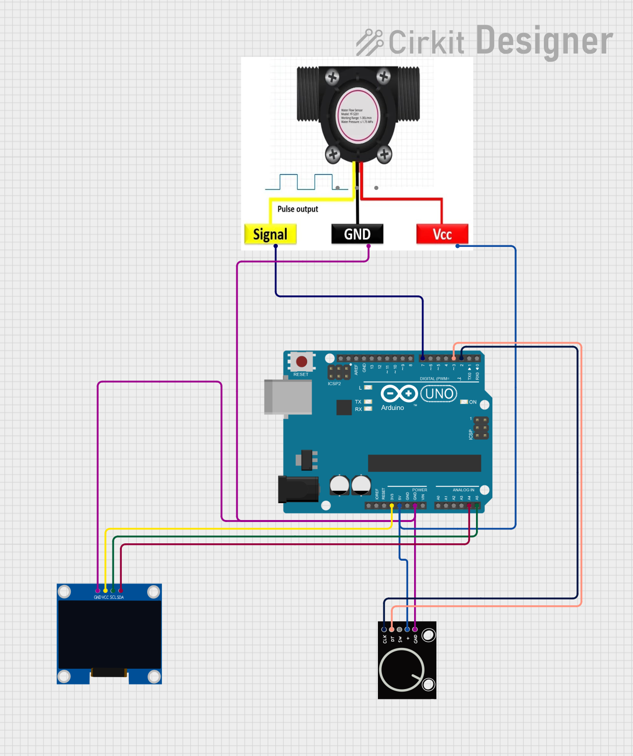
| Connector Type | 3-pin (VCC, GND, Signal) |
Pin Configuration and Descriptions
The WaterFlow sensor typically has a 3-pin connector. Below is the pinout description:
| Pin | Name | Description |
|---|---|---|
| 1 | VCC | Power supply input (5V to 24V DC) |
| 2 | GND | Ground connection |
| 3 | Signal | Outputs a pulse signal proportional to the flow rate |
Usage Instructions
How to Use the WaterFlow Sensor in a Circuit
- Power the Sensor: Connect the VCC pin to a 5V to 24V DC power source and the GND pin to the ground of your circuit.
- Read the Signal: Connect the Signal pin to a microcontroller (e.g., Arduino UNO) to read the pulse output. Each pulse corresponds to a specific volume of water passing through the sensor.
- Calculate Flow Rate: Use the pulse frequency to calculate the flow rate. The sensor's datasheet typically provides a formula or calibration constant for this calculation.
Important Considerations and Best Practices
- Water Quality: Ensure the water is free of debris or particles that could damage the sensor's turbine.
- Orientation: Install the sensor in the correct orientation as indicated by the arrow on the housing.
- Pressure Limits: Do not exceed the maximum water pressure rating to avoid damaging the sensor.
- Calibration: For accurate measurements, calibrate the sensor using a known flow rate and adjust the calculation formula accordingly.
Example Code for Arduino UNO
Below is an example of how to use the WaterFlow sensor with an Arduino UNO to measure and display the flow rate:
// WaterFlow Sensor Example Code for Arduino UNO
// Measures water flow rate and displays it on the Serial Monitor

const int sensorPin = 2; // Signal pin connected to digital pin 2
volatile int pulseCount = 0; // Variable to store pulse count
float flowRate = 0.0; // Variable to store flow rate in L/min
unsigned long lastTime = 0; // Time of the last calculation
const unsigned long interval = 1000; // Interval for flow rate calculation (1 second)

// Interrupt service routine to count pulses
void pulseCounter() {
  pulseCount++;
}

void setup() {
  pinMode(sensorPin, INPUT_PULLUP); // Set sensor pin as input with pull-up resistor
  attachInterrupt(digitalPinToInterrupt(sensorPin), pulseCounter, RISING);
  Serial.begin(9600); // Initialize Serial communication
}

void loop() {
  unsigned long currentTime = millis();

  // Calculate flow rate every second
  if (currentTime - lastTime >= interval) {
    lastTime = currentTime;

    // Calculate flow rate in L/min
    // Example: If the sensor outputs 450 pulses per liter
    flowRate = (pulseCount / 450.0) * 60.0;
    pulseCount = 0; // Reset pulse count for the next interval

    // Display flow rate on Serial Monitor
    Serial.print("Flow Rate: ");
    Serial.print(flowRate);
    Serial.println(" L/min");
  }
}
Notes:
- Replace
450.0in the formula with the actual pulses per liter value from your sensor's datasheet. - Ensure the sensor is properly calibrated for accurate results.
Troubleshooting and FAQs
Common Issues and Solutions
No Signal Output:
- Check the power supply voltage and ensure it matches the sensor's requirements.
- Verify all connections, especially the Signal pin to the microcontroller.
Inaccurate Flow Rate:
- Ensure the sensor is installed in the correct orientation.
- Calibrate the sensor using a known flow rate and adjust the calculation formula.
Intermittent Readings:
- Check for loose or faulty wiring.
- Ensure the water flow is steady and within the sensor's operating range.
Sensor Damage:
- Avoid exceeding the maximum pressure or temperature ratings.
- Use a filter to prevent debris from entering the sensor.
FAQs
Q: Can the WaterFlow sensor measure other liquids besides water?
A: While designed for water, some sensors may work with other low-viscosity, non-corrosive liquids. Check the datasheet for compatibility.
Q: How do I know the calibration constant for my sensor?
A: The calibration constant (e.g., pulses per liter) is typically provided in the sensor's datasheet or user manual.
Q: Can I use the WaterFlow sensor with a 3.3V microcontroller?
A: Yes, but ensure the Signal pin output is compatible with the microcontroller's input voltage levels. Use a level shifter if necessary.
Q: How do I clean the sensor?
A: Disconnect the sensor and flush it with clean water. Avoid using harsh chemicals or abrasive tools.
By following this documentation, you can effectively integrate and troubleshoot the WaterFlow sensor in your projects.