Cirkit Designer Logo
Cirkit Designer
Your all-in-one circuit design IDE
Home / 
Component Documentation

How to Use YHDC Current Sensor - HSTS016L- 200A : Examples, Pinouts, and Specs

Image of YHDC Current Sensor - HSTS016L- 200A
Cirkit Designer LogoDesign with YHDC Current Sensor - HSTS016L- 200A in Cirkit Designer

Introduction

The YHDC HSTS016L-200A is a high-precision Hall effect split-core current sensor designed to measure currents up to 200A. This sensor is ideal for applications requiring non-intrusive current measurement, such as power monitoring, renewable energy systems, electric vehicles, and industrial automation. Its split-core design allows for easy installation without disconnecting existing wiring, making it a versatile and user-friendly solution.

Explore Projects Built with YHDC Current Sensor - HSTS016L- 200A

Use Cirkit Designer to design, explore, and prototype these projects online. Some projects support real-time simulation. Click "Open Project" to start designing instantly!
Wemos S2 Mini Controlled Smart Device with OLED Display, Thermal Printing, and RGB LED Strip
Image of DT NEA - Noah Patel: A project utilizing YHDC Current Sensor - HSTS016L- 200A  in a practical application
This circuit features a Wemos S2 Mini microcontroller that controls a WS2812 RGB LED strip and communicates with a 0.96" OLED display and a 58mm mini thermal printer. The ACS712 Current Sensor is interfaced with the microcontroller to monitor current, and power is managed by a CD42 BMS connected to two 18650 Li-ion batteries, with a USB-C PD Trigger Board for power delivery. The circuit is designed for visual output (LED strip, OLED display), printing capabilities, and current sensing, likely for a portable, battery-powered monitoring and display device.
Cirkit Designer LogoOpen Project in Cirkit Designer
STM32 Nucleo F303RE Based Current Monitoring System with LCD Display
Image of Project BMS: A project utilizing YHDC Current Sensor - HSTS016L- 200A  in a practical application
This circuit features a current sensor connected to a 7V battery, with the sensor's output connected to an STM32 Nucleo F303RE microcontroller for current monitoring. An NTC thermistor is interfaced with the microcontroller for temperature sensing, and a 16x2 LCD screen is connected via I2C for data display. The circuit includes various resistors for voltage division and current limiting purposes.
Cirkit Designer LogoOpen Project in Cirkit Designer
ESP32-Based Current Monitoring and Temperature Sensing System
Image of SISTEMA DE MONITOREO: A project utilizing YHDC Current Sensor - HSTS016L- 200A  in a practical application
This circuit is designed to measure current using an ACS712 Current Sensor and temperature using a DS18B20 sensor, with an ESP32 microcontroller to process and possibly communicate the sensor data. The ACS712 sensor output is connected to one of the ESP32's analog input pins (D34), while the DS18B20's signal line is interfaced with a digital input pin (D23) through a pull-up resistor (4.7k Ohms). The ESP32 is powered through its Vin pin, and both sensors share a common ground with the ESP32.
Cirkit Designer LogoOpen Project in Cirkit Designer
ESP32-Based Smart Power Monitoring System with OLED Display and Wi-Fi Connectivity
Image of Circle4Life test: A project utilizing YHDC Current Sensor - HSTS016L- 200A  in a practical application
This circuit is a monitoring system using an ESP32 microcontroller to read data from multiple ACS712 current sensors and DC voltage sensors, displaying the information on a 0.96" OLED screen. The system also includes pushbuttons for user interaction and connects to WiFi for data transmission.
Cirkit Designer LogoOpen Project in Cirkit Designer

Explore Projects Built with YHDC Current Sensor - HSTS016L- 200A

Use Cirkit Designer to design, explore, and prototype these projects online. Some projects support real-time simulation. Click "Open Project" to start designing instantly!
Image of DT NEA - Noah Patel: A project utilizing YHDC Current Sensor - HSTS016L- 200A  in a practical application
Wemos S2 Mini Controlled Smart Device with OLED Display, Thermal Printing, and RGB LED Strip
This circuit features a Wemos S2 Mini microcontroller that controls a WS2812 RGB LED strip and communicates with a 0.96" OLED display and a 58mm mini thermal printer. The ACS712 Current Sensor is interfaced with the microcontroller to monitor current, and power is managed by a CD42 BMS connected to two 18650 Li-ion batteries, with a USB-C PD Trigger Board for power delivery. The circuit is designed for visual output (LED strip, OLED display), printing capabilities, and current sensing, likely for a portable, battery-powered monitoring and display device.
Cirkit Designer LogoOpen Project in Cirkit Designer
Image of Project BMS: A project utilizing YHDC Current Sensor - HSTS016L- 200A  in a practical application
STM32 Nucleo F303RE Based Current Monitoring System with LCD Display
This circuit features a current sensor connected to a 7V battery, with the sensor's output connected to an STM32 Nucleo F303RE microcontroller for current monitoring. An NTC thermistor is interfaced with the microcontroller for temperature sensing, and a 16x2 LCD screen is connected via I2C for data display. The circuit includes various resistors for voltage division and current limiting purposes.
Cirkit Designer LogoOpen Project in Cirkit Designer
Image of SISTEMA DE MONITOREO: A project utilizing YHDC Current Sensor - HSTS016L- 200A  in a practical application
ESP32-Based Current Monitoring and Temperature Sensing System
This circuit is designed to measure current using an ACS712 Current Sensor and temperature using a DS18B20 sensor, with an ESP32 microcontroller to process and possibly communicate the sensor data. The ACS712 sensor output is connected to one of the ESP32's analog input pins (D34), while the DS18B20's signal line is interfaced with a digital input pin (D23) through a pull-up resistor (4.7k Ohms). The ESP32 is powered through its Vin pin, and both sensors share a common ground with the ESP32.
Cirkit Designer LogoOpen Project in Cirkit Designer
Image of Circle4Life test: A project utilizing YHDC Current Sensor - HSTS016L- 200A  in a practical application
ESP32-Based Smart Power Monitoring System with OLED Display and Wi-Fi Connectivity
This circuit is a monitoring system using an ESP32 microcontroller to read data from multiple ACS712 current sensors and DC voltage sensors, displaying the information on a 0.96" OLED screen. The system also includes pushbuttons for user interaction and connects to WiFi for data transmission.
Cirkit Designer LogoOpen Project in Cirkit Designer

Common Applications

  • Power monitoring in residential, commercial, and industrial settings
  • Renewable energy systems (e.g., solar inverters, wind turbines)
  • Electric vehicle charging stations
  • Industrial automation and motor control
  • Overcurrent protection and fault detection

Technical Specifications

Below are the key technical details of the YHDC HSTS016L-200A current sensor:

Parameter Value
Manufacturer YHDC
Part Number HSTS016L
Measurement Range 0A to 200A AC
Output Signal 0V to 5V DC (proportional to input current)
Supply Voltage 5V DC
Accuracy ±1%
Operating Temperature -25°C to +70°C
Core Type Split-core
Isolation Voltage 2.5kV
Dimensions 50mm x 50mm x 20mm
Weight 150g

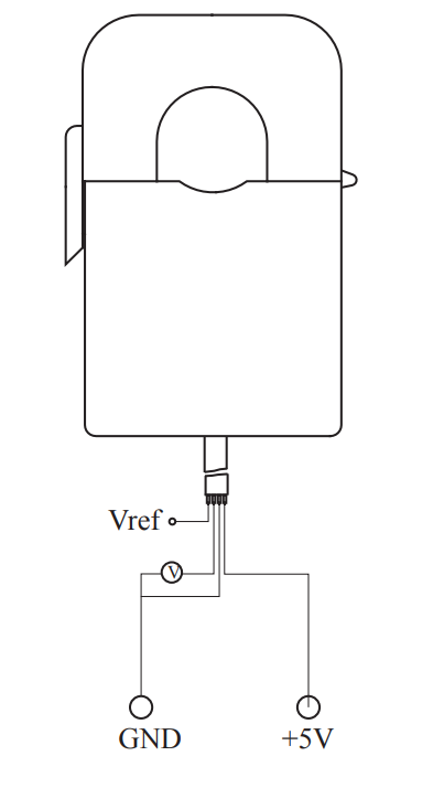
Pin Configuration and Descriptions

The HSTS016L-200A has a simple 3-pin interface for easy integration into circuits. The pinout is as follows:

Pin Name Description
1 VCC Power supply input (5V DC)
2 GND Ground connection
3 VOUT Analog output voltage proportional to measured current

Usage Instructions

How to Use the HSTS016L-200A in a Circuit

  1. Power Supply: Connect the VCC pin to a stable 5V DC power source and the GND pin to the ground of your circuit.
  2. Current Measurement: Open the split-core clamp and place it around the conductor carrying the current to be measured. Ensure the conductor is centered within the core for optimal accuracy.
  3. Output Signal: The VOUT pin provides an analog voltage proportional to the current flowing through the conductor. This output can be read using an ADC (Analog-to-Digital Converter) on a microcontroller or data acquisition system.

Important Considerations

  • Polarity: Ensure the current flow direction matches the sensor's orientation markings for accurate readings.
  • Calibration: For precise measurements, calibrate the sensor by comparing its output with a known reference current.
  • Noise Reduction: Use proper shielding and grounding techniques to minimize noise in the output signal.
  • Maximum Current: Do not exceed the 200A maximum current rating to avoid damaging the sensor.

Example: Connecting to an Arduino UNO

The HSTS016L-200A can be easily interfaced with an Arduino UNO to measure current. Below is an example circuit and code:

Circuit Connections

  • Connect the VCC pin of the sensor to the 5V pin on the Arduino.
  • Connect the GND pin of the sensor to the GND pin on the Arduino.
  • Connect the VOUT pin of the sensor to the A0 analog input pin on the Arduino.

Arduino Code

// YHDC HSTS016L-200A Current Sensor Example Code
// This code reads the sensor's output and calculates the current in amperes.

const int sensorPin = A0;  // Analog pin connected to VOUT of the sensor
const float sensitivity = 0.025; // Sensitivity in volts per ampere (example: 0.025V/A)
const float vRef = 5.0;    // Reference voltage of the Arduino (5V)
const int adcResolution = 1024; // ADC resolution (10-bit for Arduino UNO)

void setup() {
  Serial.begin(9600); // Initialize serial communication
}

void loop() {
  int sensorValue = analogRead(sensorPin); // Read the analog value from the sensor
  float voltage = (sensorValue * vRef) / adcResolution; // Convert ADC value to voltage
  float current = voltage / sensitivity; // Calculate current in amperes

  // Print the current value to the Serial Monitor
  Serial.print("Current: ");
  Serial.print(current);
  Serial.println(" A");

  delay(1000); // Wait for 1 second before the next reading
}

Notes:

  • Adjust the sensitivity value in the code based on the sensor's datasheet or calibration results.
  • Ensure the Arduino's ADC reference voltage matches the actual supply voltage for accurate readings.

Troubleshooting and FAQs

Common Issues and Solutions

  1. No Output Signal

    • Cause: Incorrect wiring or insufficient power supply.
    • Solution: Verify all connections and ensure the sensor is powered with 5V DC.
  2. Inaccurate Readings

    • Cause: Improper calibration or external noise interference.
    • Solution: Calibrate the sensor using a known reference current and minimize noise by using shielded cables.
  3. Output Voltage Exceeds Expected Range

    • Cause: Current exceeds the sensor's 200A limit.
    • Solution: Ensure the measured current is within the sensor's specified range.
  4. Sensor Overheating

    • Cause: Prolonged exposure to high currents or ambient temperatures.
    • Solution: Operate the sensor within its specified temperature and current limits.

FAQs

Q: Can the HSTS016L-200A measure DC current?
A: No, this sensor is designed for AC current measurement only.

Q: How do I ensure accurate readings?
A: Center the conductor within the split-core, calibrate the sensor, and minimize noise in the circuit.

Q: Is the sensor compatible with 3.3V systems?
A: The sensor requires a 5V power supply, but its output can be interfaced with 3.3V systems using a voltage divider or level shifter.

Q: Can I use this sensor for high-frequency applications?
A: The sensor is suitable for standard AC power frequencies (50/60Hz). For high-frequency applications, consult the manufacturer for compatibility.