Cirkit Designer Logo
Cirkit Designer
Your all-in-one circuit design IDE
Home / 
Component Documentation

How to Use 940nm Infrared LED Transmitter Module: Examples, Pinouts, and Specs

Image of 940nm Infrared LED Transmitter Module
Cirkit Designer LogoDesign with 940nm Infrared LED Transmitter Module in Cirkit Designer

Introduction

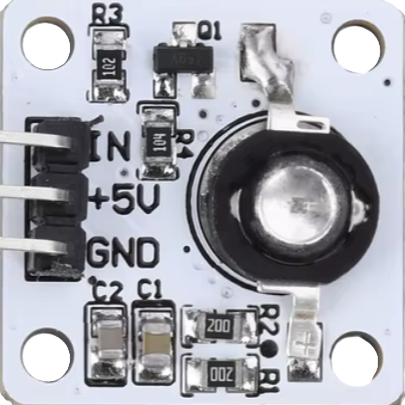
The 940nm Infrared LED Transmitter Module is a versatile electronic component designed to emit infrared light at a wavelength of 940 nanometers. This module is commonly used in remote control systems, communication applications, and various sensing technologies. Its ability to transmit infrared light makes it an essential component in devices such as TV remotes, IR communication systems, and proximity sensors.

Explore Projects Built with 940nm Infrared LED Transmitter Module

Use Cirkit Designer to design, explore, and prototype these projects online. Some projects support real-time simulation. Click "Open Project" to start designing instantly!
433 MHz RF Transmitter and Receiver with Arduino Uno for Wireless LED Control
Image of rf module up: A project utilizing 940nm Infrared LED Transmitter Module in a practical application
This circuit consists of two Arduino Uno R3 microcontrollers communicating wirelessly using 433 MHz RF modules. One Arduino is connected to an RF transmitter to send data, while the other Arduino is connected to an RF receiver to receive data and control an LED based on the received signal.
Cirkit Designer LogoOpen Project in Cirkit Designer
IR Sensor-Controlled Relay with LED Indicator
Image of smart TV: A project utilizing 940nm Infrared LED Transmitter Module in a practical application
This circuit uses an IR sensor to control a relay module, which in turn switches a 12V blue LED on and off. The IR sensor output is connected to the signal input of the relay, enabling the sensor to activate the relay. The relay's normally closed (NC) contact is connected to the LED, allowing the LED to be powered by a 9V battery when the relay is not activated by the IR sensor.
Cirkit Designer LogoOpen Project in Cirkit Designer
Battery-Powered Laser Emitter with Solar Charging and LED Indicator
Image of rx: A project utilizing 940nm Infrared LED Transmitter Module in a practical application
This circuit is a solar-powered laser emitter system with an LED indicator. The solar panel charges a 18650 battery via a TP4056 charging module, and a push button controls the activation of the laser emitter and the LED through a MOSFET switch.
Cirkit Designer LogoOpen Project in Cirkit Designer
Arduino Nano-Based Motion Detection and Distance Measurement System with IR Control
Image of Transmitter: A project utilizing 940nm Infrared LED Transmitter Module in a practical application
This circuit is designed to interface an Arduino Nano with an ultrasonic distance sensor (HC-SR04), a passive infrared (PIR) motion sensor (HC-SR501), and an infrared (IR) receiver (TSOP312). The Arduino controls an LED through a resistor and is powered by a 18650 Li-ion battery pack. The system is likely intended for distance measurement, motion detection, and IR signal reception, with visual indication provided by the LED.
Cirkit Designer LogoOpen Project in Cirkit Designer

Explore Projects Built with 940nm Infrared LED Transmitter Module

Use Cirkit Designer to design, explore, and prototype these projects online. Some projects support real-time simulation. Click "Open Project" to start designing instantly!
Image of rf module up: A project utilizing 940nm Infrared LED Transmitter Module in a practical application
433 MHz RF Transmitter and Receiver with Arduino Uno for Wireless LED Control
This circuit consists of two Arduino Uno R3 microcontrollers communicating wirelessly using 433 MHz RF modules. One Arduino is connected to an RF transmitter to send data, while the other Arduino is connected to an RF receiver to receive data and control an LED based on the received signal.
Cirkit Designer LogoOpen Project in Cirkit Designer
Image of smart TV: A project utilizing 940nm Infrared LED Transmitter Module in a practical application
IR Sensor-Controlled Relay with LED Indicator
This circuit uses an IR sensor to control a relay module, which in turn switches a 12V blue LED on and off. The IR sensor output is connected to the signal input of the relay, enabling the sensor to activate the relay. The relay's normally closed (NC) contact is connected to the LED, allowing the LED to be powered by a 9V battery when the relay is not activated by the IR sensor.
Cirkit Designer LogoOpen Project in Cirkit Designer
Image of rx: A project utilizing 940nm Infrared LED Transmitter Module in a practical application
Battery-Powered Laser Emitter with Solar Charging and LED Indicator
This circuit is a solar-powered laser emitter system with an LED indicator. The solar panel charges a 18650 battery via a TP4056 charging module, and a push button controls the activation of the laser emitter and the LED through a MOSFET switch.
Cirkit Designer LogoOpen Project in Cirkit Designer
Image of Transmitter: A project utilizing 940nm Infrared LED Transmitter Module in a practical application
Arduino Nano-Based Motion Detection and Distance Measurement System with IR Control
This circuit is designed to interface an Arduino Nano with an ultrasonic distance sensor (HC-SR04), a passive infrared (PIR) motion sensor (HC-SR501), and an infrared (IR) receiver (TSOP312). The Arduino controls an LED through a resistor and is powered by a 18650 Li-ion battery pack. The system is likely intended for distance measurement, motion detection, and IR signal reception, with visual indication provided by the LED.
Cirkit Designer LogoOpen Project in Cirkit Designer

Technical Specifications

Key Technical Details

Parameter Value
Wavelength 940 nm
Forward Voltage 1.2V - 1.4V
Forward Current 20mA
Power Dissipation 100mW
Viewing Angle 20° - 30°
Operating Temperature -40°C to +85°C

Pin Configuration and Descriptions

Pin Number Pin Name Description
1 VCC Power supply (typically 3.3V or 5V)
2 GND Ground
3 OUT Output signal (connect to microcontroller)

Usage Instructions

How to Use the Component in a Circuit

  1. Power Supply: Connect the VCC pin to a power supply (3.3V or 5V) and the GND pin to the ground.
  2. Output Signal: Connect the OUT pin to a digital output pin of a microcontroller (e.g., Arduino UNO).
  3. Current Limiting Resistor: It is recommended to use a current-limiting resistor (typically 220Ω) in series with the VCC pin to prevent excessive current flow.

Example Circuit Diagram

  +5V (Arduino) ----->|----[220Ω]----|----> VCC (Module)
                      |              |
                     GND            OUT
                      |              |
                    (GND)          (Digital Pin)

Important Considerations and Best Practices

  • Current Limiting: Always use a current-limiting resistor to protect the LED from excessive current.
  • Viewing Angle: Position the LED to ensure the emitted IR light is directed towards the intended receiver.
  • Ambient Light: Minimize ambient light interference for better performance in communication applications.

Arduino UNO Example Code

/*
  Example code to control a 940nm Infrared LED Transmitter Module
  using an Arduino UNO. This code will turn the IR LED on and off
  at 1-second intervals.
*/

const int irLedPin = 9; // Pin connected to the OUT pin of the module

void setup() {
  pinMode(irLedPin, OUTPUT); // Set the pin as an output
}

void loop() {
  digitalWrite(irLedPin, HIGH); // Turn the IR LED on
  delay(1000); // Wait for 1 second
  digitalWrite(irLedPin, LOW); // Turn the IR LED off
  delay(1000); // Wait for 1 second
}

Troubleshooting and FAQs

Common Issues Users Might Face

  1. IR LED Not Emitting Light:

    • Solution: Ensure the power supply is connected correctly and the current-limiting resistor is in place. Verify the connections and check for any loose wires.
  2. Weak Signal Reception:

    • Solution: Adjust the position of the IR LED to ensure it is directed towards the receiver. Reduce ambient light interference.
  3. Overheating:

    • Solution: Check the current-limiting resistor value. Ensure it is appropriate to limit the current to 20mA.

FAQs

Q1: Can I use a higher voltage power supply?

  • A1: No, using a higher voltage than specified (3.3V or 5V) can damage the module. Always use the recommended voltage.

Q2: How can I test if the IR LED is working?

  • A2: Use a digital camera or smartphone camera to view the IR LED. When the LED is on, it will appear as a faint light on the camera screen.

Q3: Can I use this module for data communication?

  • A3: Yes, the 940nm Infrared LED Transmitter Module is suitable for data communication applications, such as remote controls and IR communication systems.

By following this documentation, users can effectively integrate the 940nm Infrared LED Transmitter Module into their projects, ensuring optimal performance and reliability.